
Contents
1. Introduction
In previous experiments, we used the INPUT mode to read the status of the keys. But you may have noticed a problem: the keys sometimes malfunction — even when you release the key, the output in the serial monitor remains unchanged. What's going on here?
In this lesson, we will clarify this issue and introduce a key concept: pull-up and pull-down resistors. Finally, we will conduct a practical experiment — "Key Control LED Light" — to apply pull-up and pull-down resistors to help you consolidate what you have learned.
2. Why is the key reading unstable?
Let's review our control logic
- When the key is pressed, the circuit is closed, the GPIO pin is connected to VCC, and a high level (1) should be read.
- When the key is released, the circuit is disconnected, and the GPIO pin should read a low level (0).
However, during actual operation, you may notice some strange phenomena:
The button was not pressed, but the program displayed it as "pressed".
Running the same code several times will result in different reading results each time.
This is not a bug in your code, but a classic "pitfall" in hardware circuits — floating pins.
2.1 Cause Analysis
Let's conduct a detailed analysis of the circuit logic for button control:
- When pressed, the pin is connected to VCC, and the reading is a high level, which is normal.
- When released, the pin disconnects, meaning it is neither connected to VCC nor to GND.
This means: the pin is neither at a high level nor a low level —— it is connected to "nothing but air".
The problem lies precisely in this step.
2.2 Floating Pins
We refer to the situation where a pin is not connected to any valid voltage source as a floating pin.
What happens when reading a floating pin? To verify this, we can conduct a simple experiment:
- Set the pin to
INPUTmode; - In the
loop ()function, usedigitalRead ()to continuously read its state; - Print the results using
Serial.print (); - Add a little
delay ()for easier observation; - Try several unconnected pins and output signals simultaneously.
08-1 Floating Pin Output Debug Information - Wokwi ESP32, STM32, Arduino Simulator
void setup() {
   Serial.begin(115200);                // communication baud rate 115200

   pinMode(2,INPUT);                   // set pin 2 as input mode
   pinMode(4,INPUT);                   // set pin 4 as input mode
   pinMode(5,INPUT);                   // set pin 5 as input mode
   pinMode(12,INPUT);                   // set pin 12 as input mode
   pinMode(13,INPUT);                   // set pin 13 as input mode
   pinMode(14,INPUT);                   // set pin 14 as input mode
   pinMode(15,INPUT);                   // set pin 15 as input mode
   pinMode(18,INPUT);                   // set pin 18 as input mode
}

void loop() {
   int a2 = digitalRead(2);           // read the digital signal of pin 2
   int a4 = digitalRead(4);           // read the digital signal of pin 4
   int a5 = digitalRead(5);           // read the digital signal of pin 5
   int a12 = digitalRead(12);         // read the digital signal of pin 12
   int a13 = digitalRead(13);         // read the digital signal of pin 13
   int a14 = digitalRead(14);         // read the digital signal of pin 14
   int a15 = digitalRead(15);         // read the digital signal of pin 15
   int a18 = digitalRead(18);         // read the digital signal of pin 18

   Serial.print(a2);                // output the digital signal value over serial
   Serial.print(",");
   Serial.print(a4);                // output the digital signal value over serial
   Serial.print(",");
   Serial.print(a5);                // output the digital signal value over serial
   Serial.print(",");
   Serial.print(a12);                // output the digital signal value over serial
   Serial.print(",");
   Serial.print(a13);                // output the digital signal value over serial
   Serial.print(",");
   Serial.print(a14);                // output the digital signal value over serial
   Serial.print(",");
   Serial.print(a15);                // output the digital signal value over serial
   Serial.print(",");
   Serial.println(a18);              // output the digital signal value over serial
   delay(1000);                         // pause for one second
}
You will find that for pins not connected to any circuit, the readout values change randomly and may differ after each refresh.
This indicates that pins in a floating state do not default to a low level!
Our intuition tends to tell us: "If a pin isn't connected to anything, it should be 0, right? No voltage means a low logic level!"
Why is the reality not what we think it is now?
In a high-impedance state, the pin acts like a "no-man's land" that anyone can influence; even a tiny amount of static electricity, a finger hovering nearby, or electromagnetic fluctuations from surrounding wires can hold it at either a high or low logic level. Every time the device powers on or refreshes, the logic level read could be 1 or 0, with the value determined randomly.
3. Pull-up and pull-down resistors
So how to solve this problem? The answer is — to assign a "default logic level" to the pin. This way, even when the button is not pressed, the pin's state will not fluctuate randomly and can maintain a stable logic value (high or low). For this purpose, we introduce two common solutions: pull-up resistors and pull-down resistors.
3.1 Pull-up Resistor: Defaults to being pulled to high level
"Pull-up" means connecting the pin by default to VCC (high level) via a resistor.
- When there is no signal input, the pin will be pulled to a high level through a resistor;
- When an external signal is present (e. g., a key is grounded), the high level is overridden and a low level is read.
In this way, the level of the pin is "determined" regardless of whether there is an input signal or not.
Let's take a look at the working principle of pull-up resistors:
We connect a resistor between the pin and VCC. When the key is not pressed, current flows from VCC → resistor → pin, and the pin level is high 1.
Once you press the key, the pin is directly connected to GND: pin → GND, and the pin is effectively pulled to a low level, which is 0.
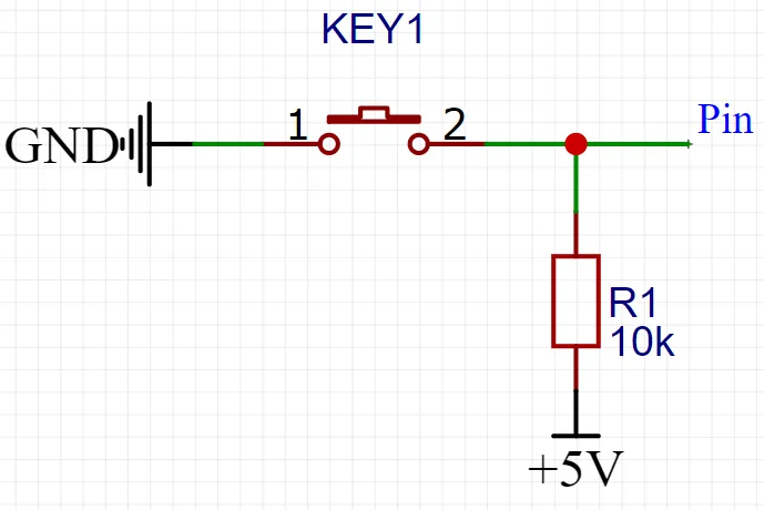
Status | Pin Level | Causes |
Key not pressed | High level (1) | The pull-up resistor provides it with a default "high" level from VCC. |
Key pressed | Low level (0) | Pressing the button directly grounds the pin, pulling the voltage level low. |
3.2 Pull-down resistor: default to pull to low level
"Pull-down" means connecting a pin by default to GND (low level) via a resistor.
- When there is no signal input, the pin is pulled to a low level by a resistor;
- When an external signal is present (for example, a key is connected to VCC), the low level is overridden, and a high level is read.
Similarly, regardless of whether there is an input signal or not, the level of the pin is "determined".
Let's take a look at the working principle of the pull-down resistor:
We connect a resistor between the pin and GND; when the key is not pressed, the current flows from the pin → resistor → GND, and the pin level is pulled low to 0.
Once you press the key, the pin is directly connected to VCC, and at this point: the current flows from VCC → key → pin → resistor → GND; the pin is effectively pulled high, which is 1.
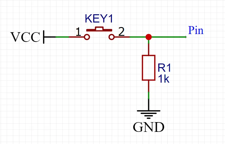
Status | Pin Level | Causes |
Key not pressed | Low level (0) | The pull-down resistor provides it with a default "low" level from GND. |
Button pressed | High level (1) | Pressing the key directly connects the pin to VCC, pulling the voltage level high. |
3.3 Software Implementation
The ESP32 also directly integrates the function of pull-up and pull-down resistors internally, which we can configure directly via code. Internal pull-up or internal pull-down is supported, eliminating the need for external resistors.
pinMode(2,INPUT_PULLUP);                 // set pin 2 as input mode, enable internal pull-up resistor
pinMode(4,INPUT_PULLDOWN);               // set pin 4 as input mode, enable internal pull-down resistor
It should be noted that GPIO34 to GPIO39 can only be configured as a normal input mode, and do not support input pull-up or input pull-down modes.
Below is a sample code that demonstrates how to enable internal pull-up resistors on multiple pins and read their states:
08-2 Input Pull-Up Mode Experiment - Wokwi ESP32, STM32, Arduino Simulator
void setup() {
   Serial.begin(115200);                // communication baud rate 115200

   pinMode(2,INPUT_PULLUP);             // set pin 2 as input mode, enable internal pull-up resistor
   pinMode(4,INPUT_PULLUP);             // set pin 4 as input mode, enable internal pull-up resistor
   pinMode(5,INPUT_PULLUP);             // set pin 5 as input mode, enable internal pull-up resistor
   pinMode(12,INPUT_PULLUP);            // set pin 12 as input mode, enable internal pull-up resistor
   pinMode(13,INPUT_PULLUP);            // set pin 13 as input mode, enable internal pull-up resistor
   pinMode(14,INPUT_PULLUP);            // set pin 14 as input mode, enable internal pull-up resistor
   pinMode(15,INPUT_PULLUP);            // set pin 15 as input mode, enable internal pull-up resistor
   pinMode(18,INPUT_PULLUP);            // set pin 18 as input mode, enable internal pull-up resistor
}

void loop() {
   int a2 = digitalRead(2);           // read the digital signal of pin 2
   int a4 = digitalRead(4);           // read the digital signal of pin 4
   int a5 = digitalRead(5);           // read the digital signal of pin 5
   int a12 = digitalRead(12);         // read the digital signal of pin 12
   int a13 = digitalRead(13);         // read the digital signal of pin 13
   int a14 = digitalRead(14);         // read the digital signal of pin 14
   int a15 = digitalRead(15);         // read the digital signal of pin 15
   int a18 = digitalRead(18);         // read the digital signal of pin 18

   Serial.print(a2);                // output the digital signal value over serial
   Serial.print(",");
   Serial.print(a4);                // output the digital signal value over serial
   Serial.print(",");
   Serial.print(a5);                // output the digital signal value over serial
   Serial.print(",");
   Serial.print(a12);                // output the digital signal value over serial
   Serial.print(",");
   Serial.print(a13);                // output the digital signal value over serial
   Serial.print(",");
   Serial.print(a14);                // output the digital signal value over serial
   Serial.print(",");
   Serial.print(a15);                // output the digital signal value over serial
   Serial.print(",");
   Serial.println(a18);              // output the digital signal value over serial
   delay(1000);                         // pause for one second
}
After the pull-up resistor is enabled, the pin will default to a high level even when it is floating, and the random pin voltage phenomenon will no longer occur.
4. Key-controlled LED
Now let's conduct a very classic experiment: to control the on/off state of an LED with a button.
4.1 Circuit Connection
Connect one end of a pushbutton to GND, and the other end to a GPIO pin, such as GPIO2;
Meanwhile, for this pin, enable the internal pull-up resistor to ensure that the pin remains at a high level when the key is not pressed;
Connect the anode (long leg) of an LED to GPIO 15, and the cathode (short leg) to GND.
4.2 Software Implementation
void setup() {
  pinMode(2, INPUT_PULLUP);   // set the button pin as input mode, enable pull-up
  pinMode(15, OUTPUT);        // set the LED pin as output mode
}

void loop() {
  int keyState = digitalRead(2); // read the button state
  if (keyState == LOW) {
    digitalWrite(15, HIGH); // button pressed, turn on the LED
  }
  else
  {
    digitalWrite(15, LOW);  // button released, turn off the LED
  }
}
After the pull-up resistor is enabled:
- When the key is not pressed, the pin is connected to VCC via a pull-up resistor, so a high level (1) is read;
- When the key is pressed, the pin is directly connected to GND, and the level is pulled low to 0;
- It is by detecting this level change in the program that the key state is determined, and the on/off of the LED is controlled accordingly.
08-3 Button Controlled LED - Input Pull-Up - Wokwi ESP32, STM32, Arduino Simulator
5. Summary of This Chapter
In this chapter, we learned about the principles and functions of pull-up resistors and pull-down resistors, and understood how they provide a stable default voltage level for input pins to prevent the pins from being in an uncertain "floating" state.
Subsequently, we conducted an experiment of controlling the on/off of an LED via a button to verify the actual application effect of pull-up resistors, and also mastered how to combine input and output to implement a complete interactive process.