
Contents
1. Introduction: Get Started with ESP32 Development by Working with GPIO
In this chapter, I will take you from code to reality—
Whether you want to light up an LED or read the input from a button, the very first thing you need to do is learn how to use GPIO.
GPIO is one of the most basic and commonly used functions of a microcontroller, and it is also the starting point for us to control hardware.
Next, we will start with the two directions of "output" and "input" of GPIO, and make the hardware actually "move" through hands-on operations.
2. Basic Concepts of GPIO
General Purpose Input/Output, a universal input-output interface.
It is the main channel for signal transmission between the ESP32 and external devices.
From the perspective of the ESP32, the GPIO is responsible for signal communication with the outside world, including input and output.
Output: control external devices to operate, control the on/off of LEDs, drive the rotation of steering gears, etc.
Input: Collect information of external devices , obtain key status, read sensor data...
3. Electrical Signals
The "language" between the ESP32 and external devices refers to electrical signals, which can be understood as changes in voltage levels that convey information such as switching commands and statuses.
For example, the ESP32 outputs a high voltage through a GPIO pin to turn on the LED, and outputs a low voltage to turn off the LED.
Conversely, when a key is pressed, the key will transmit a voltage change to the ESP32 through the GPIO pin, informing it that "the button has been pressed".
In this way, the ESP32 can control devices or read the status of buttons according to the level of the voltage.
4. High and low levels
Here, the high and low voltages are what we commonly refer to as "high level" and "low level".
ESP32 is a digital device, and the information it processes is binary, meaning that data and instructions are represented using 0s and 1s.
Physically, the binary digits 0 and 1 correspond to low and high logic levels respectively. Typically, the ESP32 recognizes a signal with a voltage higher than 2.5 volts as a high level, and a signal with a voltage lower than 0.5 volts as a low level.
It is precisely through this simple and clear voltage distinction that the ESP32 can convert digital signals into specific control commands, drive LEDs to turn on and off, read the status of buttons, or collect sensor information, so as to realize interaction with external devices.
5. Here's an LED light for you
LED (Light Emitting Diode) is an electronic component capable of emitting light, and it is also one of the components we most commonly use to test and practice GPIO output. It can intuitively indicate whether the ESP32 has successfully controlled a certain pin.
5.1 Basic Principles of LEDs
An LED is a type of diode that only allows electric current to flow in one direction. When current flows from the anode (the longer leg) to the cathode (the shorter leg), the LED will emit light.
The higher the current, the brighter the light, but if the current is too high and exceeds the range it can withstand, it will be game over.
Therefore, in practical applications, we usually connect a current-limiting resistor in series to protect the LED.
5.2 Circuit Connection
Lighting it up is also very simple — you just need to create a conductive path between the ESP32 pin and the LED.
We connect an LED in the simplest possible way:
- Connect the long leg of the LED to a GPIO pin of the ESP32 (e. g., GPIO12)
- Connect the short lead of the LED to GND (ground) via a 220Ω resistor.
Apply a high-level voltage to it again, and the LED will light up.
5.3 Experimental Code for Lighting Up an LED
Next, we will write code to make the ESP32 control pin No. 12 to output high and low levels, so as to turn the LED on and off.
in two steps: first, set pin 12 to output mode, then control pin 12 to output high and low levels.
5.3.1 Set Pin Mode
Since the GPIO pins of the ESP32 can both receive inputs (such as from pushbuttons) and output control signals (such as to light up an LED), we first need to tell the chip what a given pin is to be used for, which requires setting the "pin mode".
pinMode(12, OUTPUT); // set pin 12 as output mode5.3.2 Control the Output High and Low Levels of Pins
Use the digitalWrite () function to control pin 12 to output a high level. The first parameter is also the pin number, and the second parameter is the output level: HIGH for high level HIGH, and LOW for low level LOW.
digitalWrite(12, HIGH); // output high level, LED on
digitalWrite(12, LOW);  // output low level, LED off
5.4 Upload the complete code
Next, we will control the LED to turn on and off once every 1 second, repeating this cycle continuously.
To implement this function, you only need to add a delay function after each statement that controls the level of the control pin delay (1000), which functions to make the program "pause running" for 1000 milliseconds, which is equivalent to 1 second when converted.
Click to upload the code, and you will see that the LED blinks once every 1 second.
int ledPin = 12;  // define the GPIO pin the LED is connected to

void setup() {
  pinMode(ledPin, OUTPUT);  // set as output mode
}

void loop() {
  digitalWrite(ledPin, HIGH);  // output high level, turn on the LED
  delay(1000);                 // delay 1 second
  digitalWrite(ledPin, LOW);   // output low level, turn off the LED
  delay(1000);                 // delay 1 second
}
6.1-LED Blink - Wokwi ESP32, STM32, Arduino Simulator
6. Here's a button for you
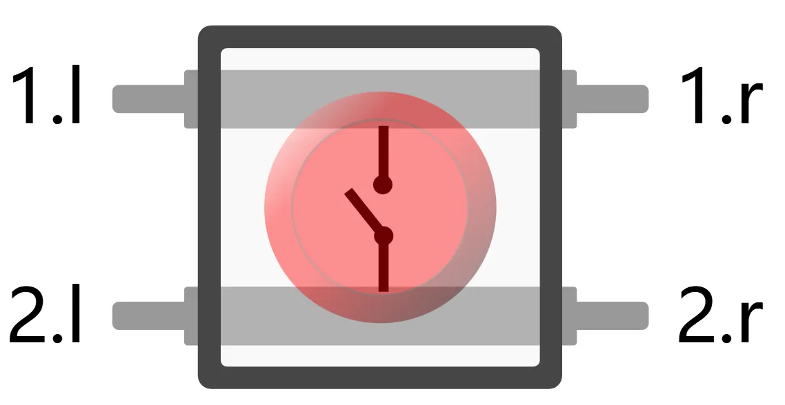
Following the LED, let's get to know another common and practical component: pushbutton (Button). It is one of the most basic human-computer interaction methods, which can be used to control the on-off state of a circuit: when the pushbutton is pressed, the circuit closes and an electrical signal is transmitted.
Learning to read the state of a key press is the first step to mastering GPIO input.
6.1 Basic Principles of Keys
A key is essentially a mechanical switch with only two states:
- Press (turn on) → the circuit closes, allowing current to flow
- Release (disconnect) → The circuit is open, and no current flows
The ESP32 determines whether the switch is pressed by reading the voltage changes on the GPIO pins.
6.2 Circuit Connection
We will connect a pushbutton in the simplest way and read its status via GPIO:
- Connect one end of the button to a GPIO pin of the ESP32 (e. g. GPIO14)
- The other end of the button is connected to GND (ground).
The corresponding status is:
- When pressed, the value read from GPIO14 is LOW
- Release → GPIO14 reads a non-low level
6.3 Experimental Code for Detecting Key Press Status
Let's write a piece of code that reads the state of the keys at regular short intervals and prints it out in the serial monitor.
The serial port section will be explained in the next section, so don't worry if you're not familiar with it, everyone!
6.3.1 Set Pin Mode
pinMode(14, INPUT); // set pin 14 as input6.3.2 Read Level Status
Then use digitalRead () to read the voltage level state of the pin:
int state = digitalRead(14); // read the level state of pin 14When state is LOW, it indicates that the button is pressed.
6.3.3 Determine the key status
Finally, use the if conditional statement to judge the key status and perform different operations.
if (buttonState == LOW)
{
    Serial.println("按钮按下");
}
else
{
    Serial.println("按钮松开");
}
6.4 Upload the complete code
We combine the above content into a complete code, and print "Button pressed" or "Button released" via the serial port each time after detecting the button state.
06-1 Button State Debug Information - Wokwi ESP32, STM32, Arduino Simulator
int buttonPin = 14;  // define the GPIO pin the button is connected to

void setup() {
  pinMode(buttonPin, INPUT);  // set as input mode
  Serial.begin(115200);       // initialize the serial port for outputting information
}

void loop() {
  int buttonState = digitalRead(buttonPin);  // read the button state

  if (buttonState == HIGH)
  {
    Serial.println("按钮按下");
  }
  else
  {
    Serial.println("按钮松开");
  }
  delay(200);  // delay 200 milliseconds to avoid flooding the output
}
Alternatively, the LED will light up once a key press is detected.
06-2 Button Controlled LED - Wokwi ESP32, STM32, Arduino Simulator
int buttonPin = 14;  // define the GPIO pin the button is connected to
int ledPin = 18;  // define the GPIO pin the LED is connected to

void setup() {
  pinMode(buttonPin, INPUT);  // set as input mode
  pinMode(ledPin, OUTPUT);  // set as input mode
  Serial.begin(115200);       // initialize the serial port for outputting information
}

void loop() {
  int buttonState = digitalRead(buttonPin);  // read the button state

  if (buttonState == HIGH)
  {
    Serial.println("按钮按下");
    digitalWrite(ledPin, HIGH);
  }
  else
  {
    Serial.println("按钮松开");
    digitalWrite(ledPin, LOW);
  }
  delay(200);  // delay 200 milliseconds to avoid flooding the output
}
Click to upload the code, open the serial monitor, press the button, and you will see the corresponding execution operation!
7. Summary of This Chapter
In this chapter, we walked you through completing your first ESP32 experimental task—— lighting up an LED, and reading the state of a pushbutton.
We have learned the following key knowledge points together:
- What are high level and low level: The ESP32 uses high and low voltage levels to represent binary 1 and 0, thereby enabling control and communication.
- How to Use GPIO Pins: Set the pin to either input mode or output mode to control external devices or read information from them.
- How to control the on/off of an LED: Output a high level to turn on the LED, and output a low level to turn off the LED.
- How to read the key status: Determine whether the key is pressed by reading the level of the GPIO input pin, and use a pull-up resistor to ensure signal stability.
Appendix: Key Bounce Counting Experiment
Button Bounce Counting Experiment - Wokwi ESP32, STM32, Arduino Simulator