
Imagine a small exhibit that lights up when someone taps its case. Getting a sensor to react is the first step. Making one tap produce one deliberate response is the part that decides whether the exhibit feels understandable or erratic.
On our bench we tried two GraftSense vibration modules, one built around an SW-520D ball switch and one around an SW-18010P spring switch, with a GraftPort-RP2040 board running MicroPython. Both showed a physical action reaching the software. The recordings also showed why a stream of electrical triggers is not yet a finished interaction: the terminal reported repeated callbacks and a full scheduling queue.
That distinction matters before you build the switch into an enclosure. In a May 2024 Arduino discussion, a developer combining vibration and motion sensors struggled with repeated readings and inconsistent timing. The module was different, but the product question was the same: which sequence of sensor activity should count as one meaningful event?
Choose the motion you want to notice
The ball switch contains moving metal balls that make or break a contact, so its orientation matters. A switch that reacts while lying near horizontal may behave differently when the circuit board is rotated inside the product. It reports a contact state; it does not measure an angle or a calibrated impact strength.
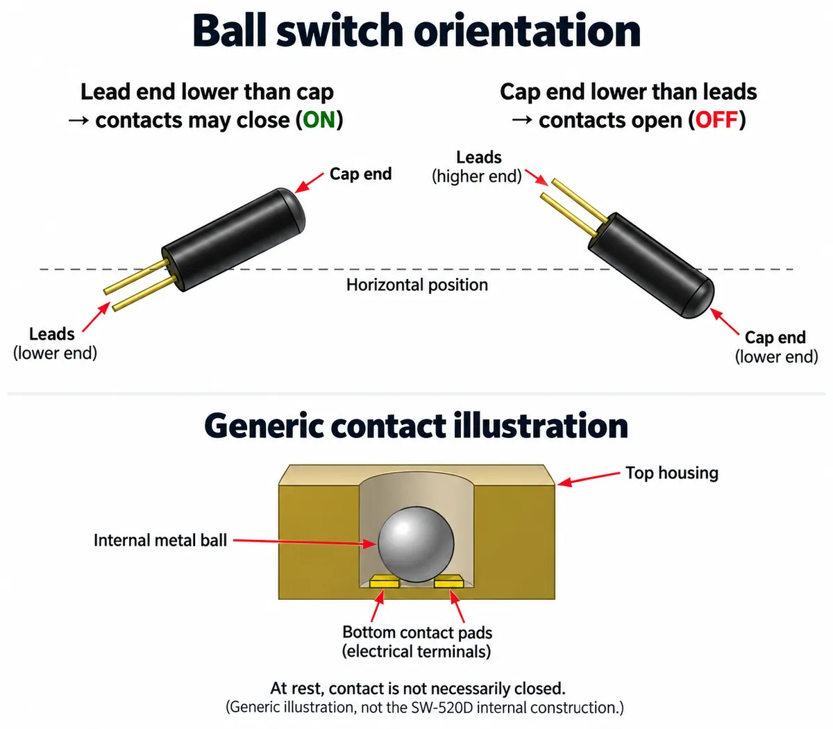
The spring switch works differently: vibration can move a conductive spring into contact with an electrode. We held the board and tapped the module by hand. For a toy or exhibit, that is a useful way to explore whether a bump is detectable before designing the final mounting.
Neither hand-held test establishes that every gentle tap will be detected, or that nearby footsteps will be ignored. Those are questions about your case, mounting and interaction. If you need to tell the force or direction of an impact, these simple switch outputs do not provide that measurement.
Follow the signal from the module to the controller
Both boards use an LM393 comparator and a small adjustment potentiometer. A comparator turns the relationship between two voltages into a digital output. Here, the switch and its resistor-capacitor network form one input, and the potentiometer sets the reference for the other. Turning it changes an electrical threshold, not a calibrated force setting.
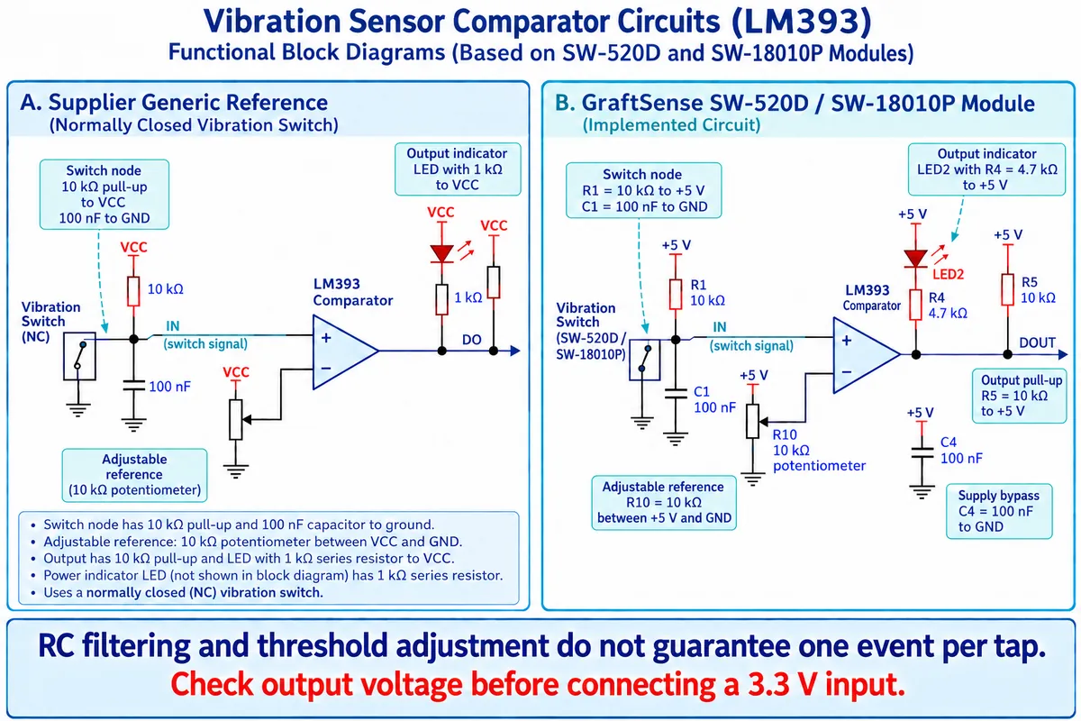
The module pulls its output up to 5 V. Before connecting it to a 3.3 V controller, establish how your specific adapter handles that signal. A four-wire connector and a working demonstration are not enough to prove safe direct wiring to a different board.
In our setup the module sat on the board's DIO0 connector, with the signal on GPIO6 and GPIO7 unused. Use your actual board revision and circuit documentation when rebuilding the setup.
This is also the point to secure the sensor mechanically. Hand-held tests are fine for initial response checks, but a loose board, a rigid mount and a flexible plastic wall transmit a tap differently. Choose the intended mounting before spending time fine-tuning the threshold.
What the test program actually ran
Our test program set up a vibration-sensor driver on GPIO6 with a callback, printed the current state every 0.2 seconds and reported a status summary periodically. The ball and spring driver packages had different package names but used the same module name, so keep each test's package and file set together.
The driver enables interrupts on both rising and falling edges. It rejects edges that arrive too soon after the last accepted edge, then asks MicroPython to run the callback later with micropython.schedule(). That interval filter reduces some repeated activity, but it does not wait for the whole mechanical motion to settle before declaring a new user action.
One more interpretation detail: the driver's read method returns bool(pin.value()), the raw high or low state. Because the module output is active-low, a printed True should not simply be relabeled "vibration detected." The code and the physical event have to be connected deliberately.
Keep the failure in the experiment
Both the ball-switch and spring-switch runs printed RuntimeError: schedule queue full between successful callbacks. The program was detecting changes, but it was also trying to queue more callbacks than the runtime could accept at those moments. That is valuable evidence to keep before adding sound, lights or communication that create more work.
The program passed a 10 ms debounce interval, although its startup message said 50 ms. Read the configuration rather than relying on a printed description. Neither value has been shown to be the right threshold for a finished tap-sensitive case.
For the next version, define the behavior in user terms. Should a shake trigger once, repeatedly while moving, or only after it stops? Should a second tap during an animation restart it or be ignored? Those choices determine how the application should combine switch transitions. Simply increasing the delay can hide events you wanted to keep.
A practical follow-up is to keep the interrupt work small, record pending activity in a flag or counter, and let the main loop decide when to produce feedback. A quiet interval after the last transition is one way to group a burst; a minimum time between accepted actions is another. They behave differently during continuous shaking. These are changes to test; we have not yet repaired the driver or rerun the tests.
Try it in the case before calling it ready
Use a short set of deliberate actions: tap the intended area, tap elsewhere, set the object down, rotate it, and leave it beside likely background movement. Record both unwanted responses and missed taps. Repeat after changing the mounting or threshold so that you know which change helped.
If the prototype reliably produces the intended response in its real case, you have a useful basis for user testing. If it reacts to everything around it, revisit the mounting, the event rule or the sensing method before committing to a PCB. A short video of the intended gesture, plus a list of the responses you want to keep or suppress, is the most useful starting point for that review.