
A test fixture receives a pulse from another device and must produce an output a known time later. Perhaps it starts an acquisition, marks an event or coordinates a low-voltage test signal. Choosing a fast PIO instruction rate on an RP2040 is useful, but it does not tell you the complete delay between the incoming edge and the outgoing one.
For a team specifying the fixture, the first question is what timing the connected equipment actually requires. A predictable delay and a delay that changes from trial to trial are different concerns. Define both the acceptable interval and its allowed variation before treating "fast" as a finished requirement.
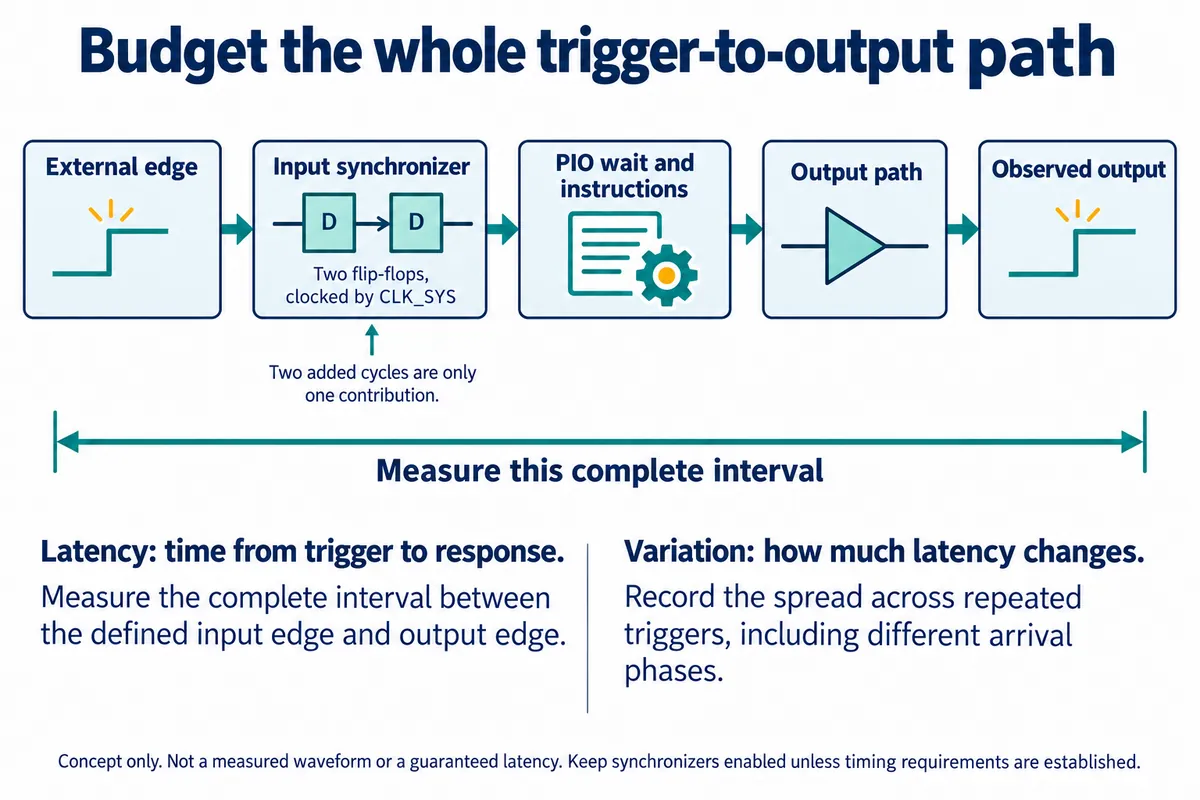
This note walks through one part of that path, the PIO input synchronizer, and how to plan a measurement around it. It is based on the datasheet and on public discussions, not on a timing capture of our own, so it gives no response-time figure.
The input has to enter the controller's clocked logic
An external signal can change between the controller's clock edges. The PIO input synchronizer gives that change time to settle before the state machine uses it. The RP2040 datasheet, section 3.5.6.3, describes a two-flip-flop synchronizer on each GPIO input, adding two cycles to input sampling. It also warns that bypassing synchronization requires meeting setup and hold timing relative to CLK_SYS.
Read that carefully: it is two flip-flops in one synchronizer per input, not two separate synchronizers. The INPUT_SYNC_BYPASS register (offset 0x038 in the PIO block) has one bit per GPIO. Zero, the reset default, keeps synchronization enabled; one bypasses it. The datasheet's own advice is to leave the register at all zeroes if in doubt.
Do not turn that bypass bit into a general speed optimization. The datasheet mentions fast synchronous I/O such as SPI as the case where bypassing may be needed. An external UART signal or an unrelated trigger does not become safely synchronous just because the PIO program is short. Removing the settling stage changes the assumptions under which the input can be sampled reliably.
Count instructions, then check what the count leaves out
The state machine must observe the input condition, execute the required instructions and drive the output through the pin path. Clock division and the arrival phase of the external signal also belong in the investigation. A wait instruction is part of this sequence; it is not a promise of zero delay at the physical pins.
A Raspberry Pi forum discussion opened October 18, 2021 describes a developer measuring the interval from an input transition to a PIO-driven output and finding a different delay from the expected instruction count. The visible discussion considers clock alignment and synchronization. It is a useful example of the question to measure, not a latency figure to copy into another design.
Measure from the event that matters to the receiving device
Choose the measurement points before looking at a trace. If the requirement concerns a connector input and a connector output, measuring only internal software markers leaves part of the path unaccounted for. If the intended result is a flash of light or a mechanical movement, an electrical output edge is an intermediate event, not the completed physical response.
Capture the input and output together with an instrument that can resolve the interval and variation you need to distinguish. Save the instrument settings, clock configuration, PIO program and wiring arrangement with the trace. A single capture shows one example interval; repeated captures are needed to understand how it varies.
Repeat with trigger arrivals that are not deliberately locked to the controller's clock, and with the rest of the prototype operating. Note missed events as well as successful ones. If the test generator shares a clock or a fixed relationship with the receiver, record that relationship: it can hide conditions that a separately clocked sensor or instrument will introduce.
Change the design only after the timing requirement is clear
If the measured response already meets the receiving equipment's needs, keeping input synchronization may be the right choice. If it does not, separate the contributions before changing the design. Instruction scheduling, interface choice and the relationship between clocks may offer different ways forward; bypassing a synchronizer is not a substitute for establishing those relationships.
The outcome for the next engineering review should be a small timing record:
- the required interval and its allowed variation;
- the measurement points at the connectors or physical output;
- the observed range across repeated, unsynchronized triggers;
- the test conditions, clock settings and program version;
- the gaps that remain untested.
That record lets the team decide whether this controller approach is suitable without mistaking an instruction frequency for a complete system guarantee.