
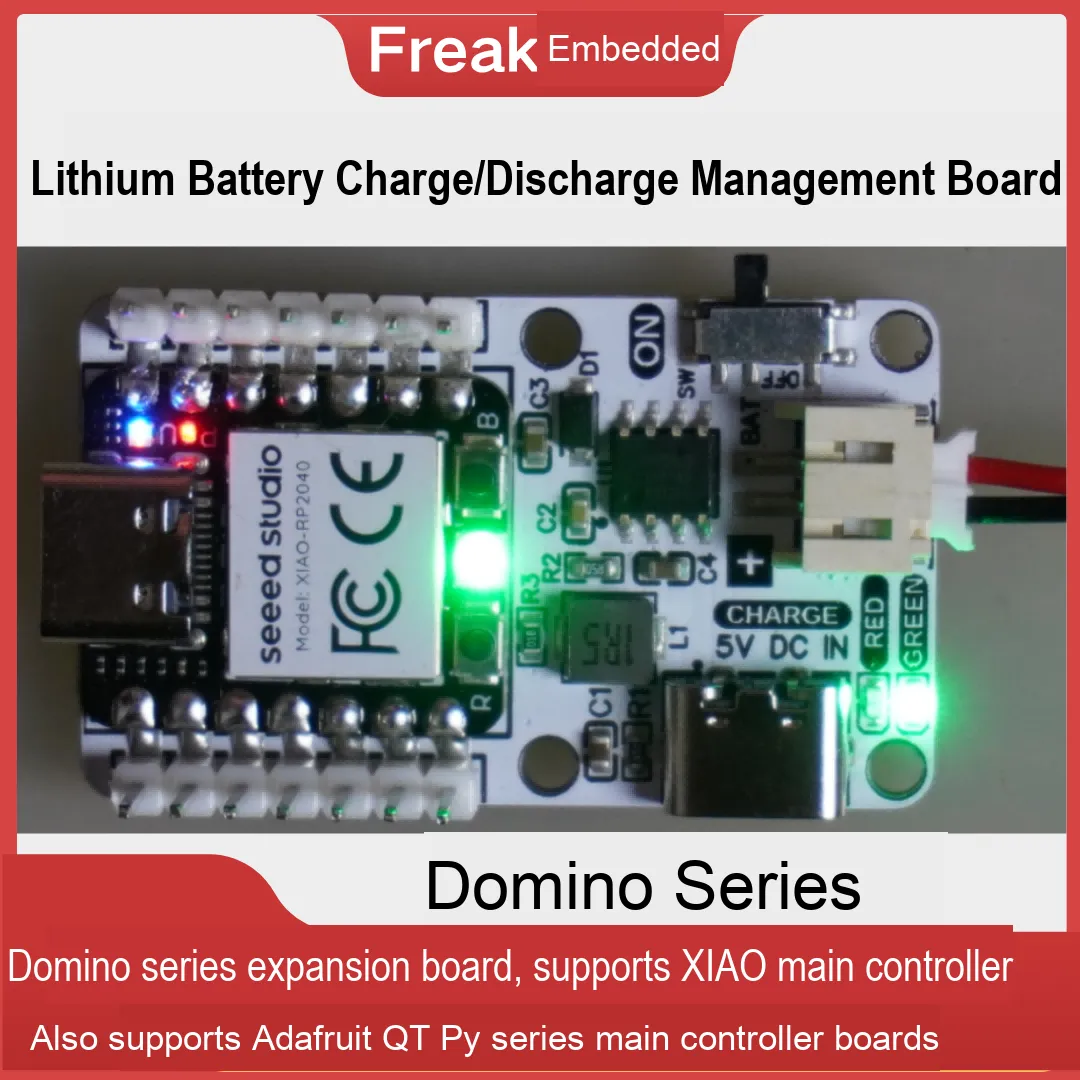
The common TP4056 lithium battery charge management chip only handles linear charging of 3.7 V lithium batteries. To implement battery protection, discharge management, or boost output, you must add a separate protection chip (PMIC), a switch/MOSFET, and a separate boost module. Here we introduce a lithium battery charge/discharge management and boost chip, the SY3501D.
The SY3501 is a single-chip solution IC designed for power banks. It is a power bank management chip that highly integrates a charge management module, an LED battery level display module, and a synchronous boost discharge management module, greatly simplifying the peripheral circuit and the number of components.
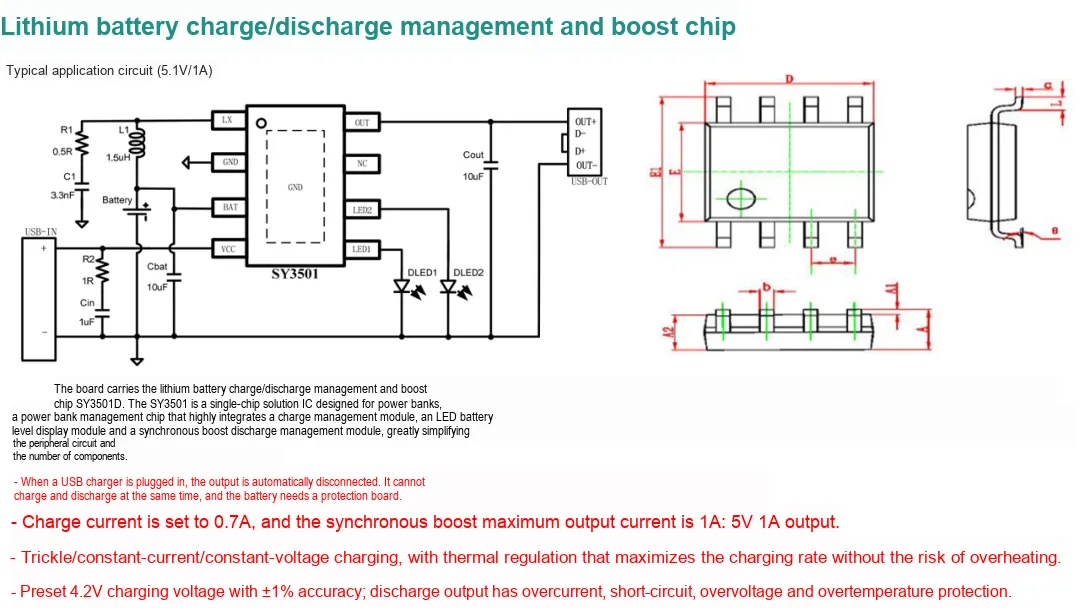
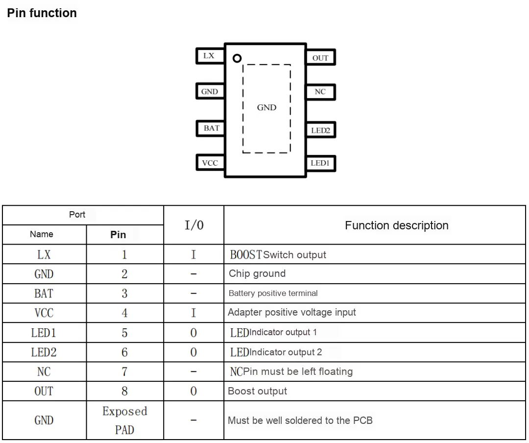
The function of each pin is described below:
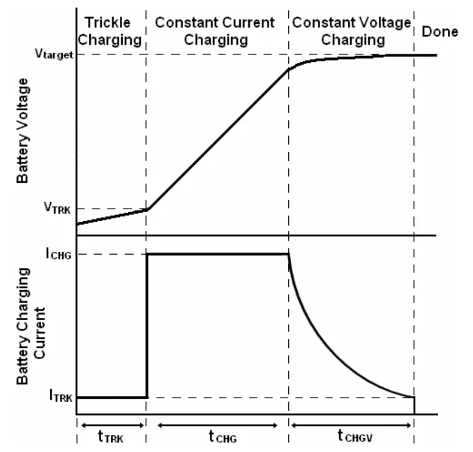
The SY3501 integrates a complete charging module and uses the internal power transistor to charge the battery with trickle, constant-current, and constant-voltage charging. The charging current is set internally by the chip, with a continuous charging current of 0.7A, so no additional current-blocking diode or current-sense resistor is needed. The chip's internal power management circuit automatically reduces the charging current when the chip junction temperature exceeds 100℃, and reduces the current to 0 once the temperature is above 140℃.
The SY3501 provides one synchronous boost output with an integrated power MOS, which can deliver a 5.1V/1A output with efficiency of up to 90%. The SY3501 uses a 1MHz switching frequency, which effectively reduces the size of external components. When no charging adapter is connected, the system always works in boost output state, with a no-load current of 100uA.
The SY3501 provides multiple abnormal-condition protections, including output overcurrent, output overvoltage, output short circuit, chip overtemperature, and battery undervoltage, which effectively protect the battery and the system. In the event of output overcurrent, output short circuit, or chip over-temperature, the SY3501 automatically shuts down the boost output and restarts after 200mS. If the fault is not cleared, the chip keeps shutting down and restarting (called hiccup mode) until the fault is cleared, after which the chip returns to normal operation. By controlling the freewheeling PMOS, the SY3501 can effectively prevent reverse current flow at the output.
It needs only 7 peripheral components to implement lithium battery charging/discharging and boost conversion. Below is the schematic that I actually tested and verified:
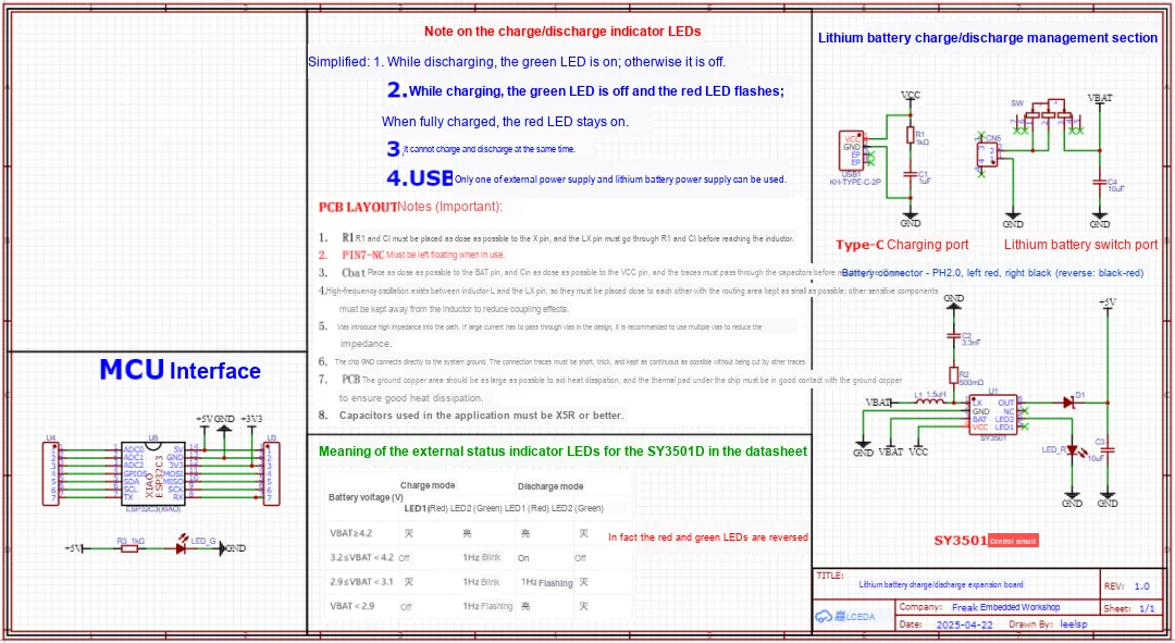
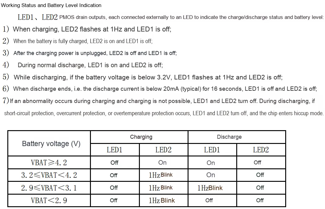
Note here that the original datasheet has an error in the charge/discharge status indicator LED section. In fact, LED1 and LED2 should be swapped:
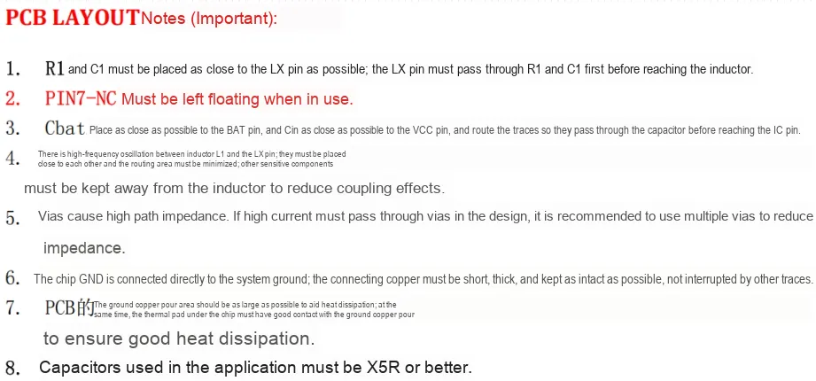
When routing the PCB, pay attention to the following details:
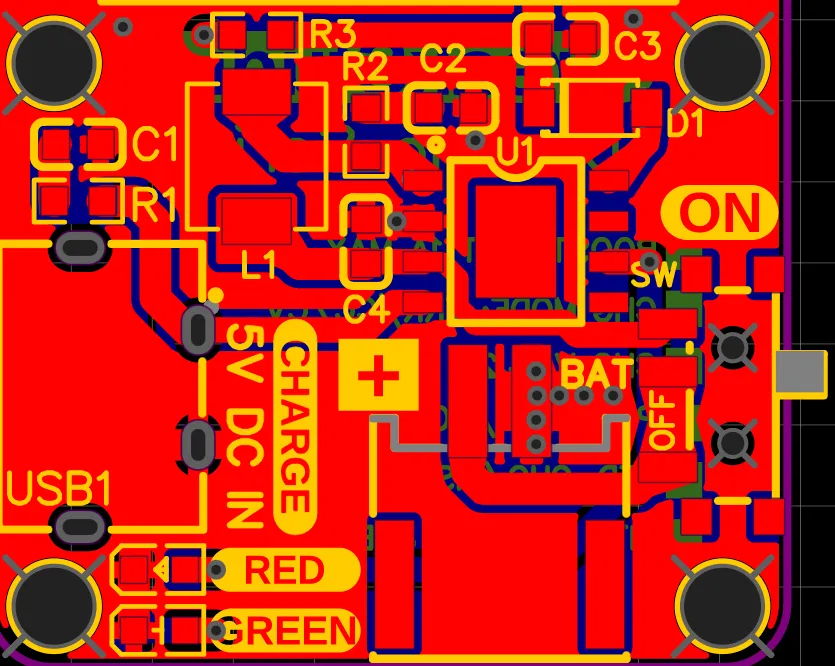
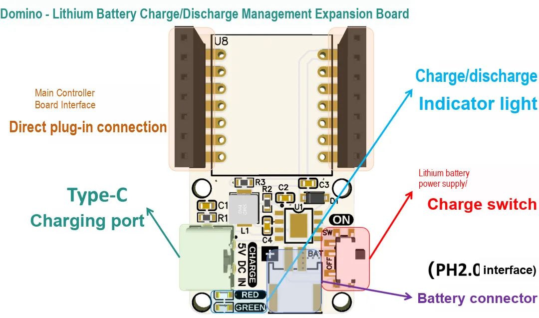
Here, I designed thislithium battery charge/discharge management boardas an expansion board for the XIAO main control board. It can be connected directly to XIAO series boards or used on its own as a standalone module:
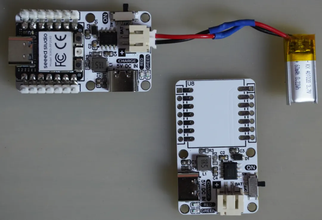
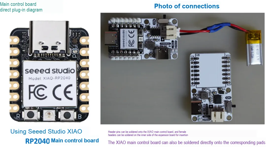
You can solder pin headers onto the XIAO main control board and solder female headers on the inner side of the expansion board to plug it in, or you can solder the XIAO main control board directly onto the corresponding pads:
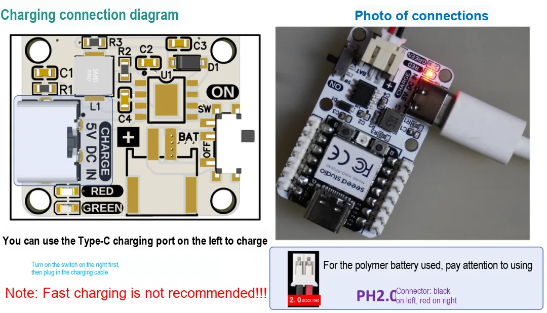
When charging, first turn on the switch on the right, then use the Type-C charging port on the left to charge:
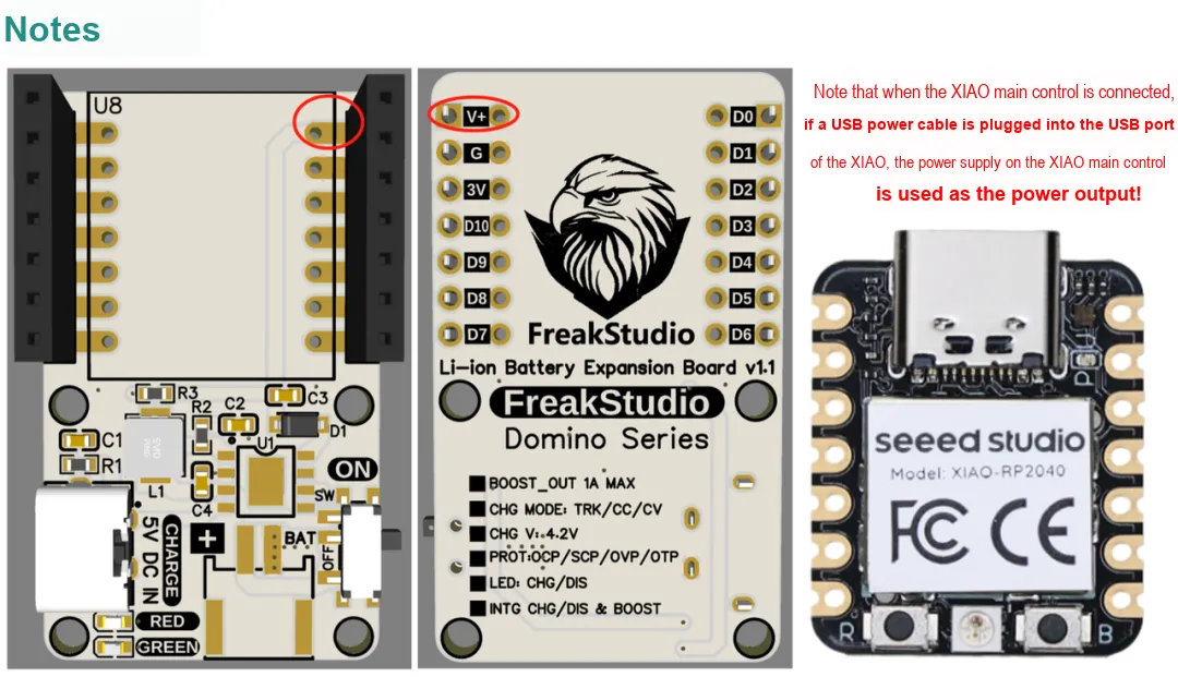
When discharging, note that when the XIAO main controller is connected, if the USB power cable is plugged into the XIAO's USB port, the power on the XIAO main controller is used as the power output:
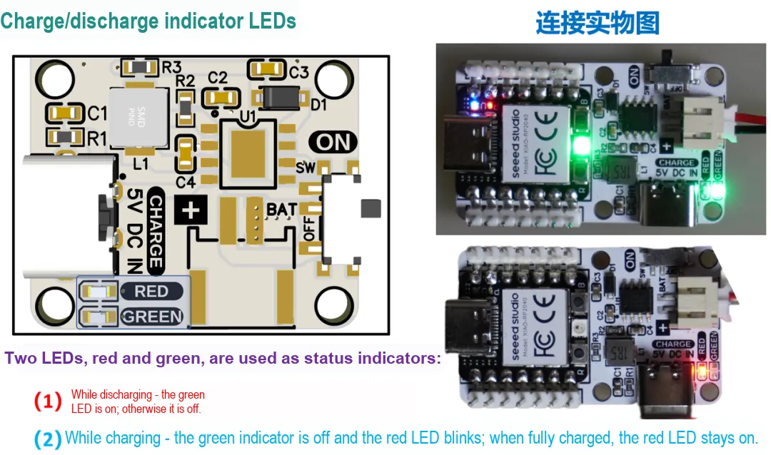
Two LEDs, red and green, are used as status indicators:
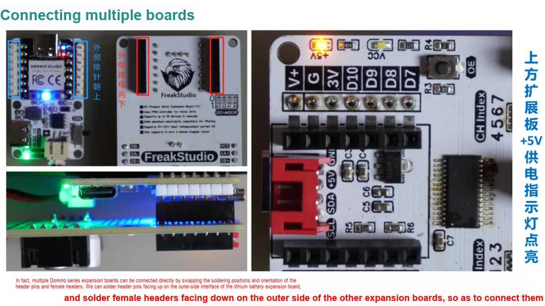
In fact, multiple Domino series expansion boards can be interconnected directly by swapping the soldering positions and directions of the pin headers and female headers. We can solder the lithium battery expansion board's
outer-side interface with upward-facing pin headers, and the other expansion boards' outer-side interfaces with downward-facing female headers, to connect them:
I have released this project on the LCSC Open Source Hub:
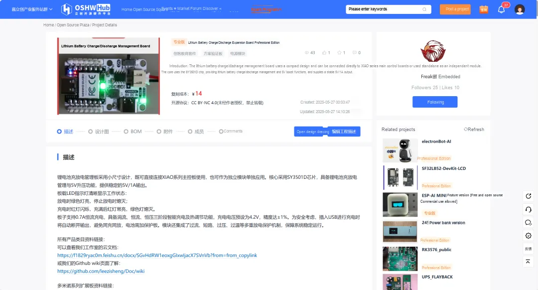
The link is:
https://oshwhub.com/freakstudio/li-dian-chi-chong-fang-dian-kuo-zhan-ban-_-zhuan-ye-ban