
Contents
- Introduction
- I. Module Introduction
- 2. Introduction to Main Chips
- 2.1 Chip Overview
- 2.2 Pin Definition
- 2.3 Functional Block Diagram
- 2.4 Performance Parameters
- 2.5 Reference Circuit
- 2.6 Chip Configuration
- 2.7 Communication Interfaces and Related Protocols
- III. Circuit Engineering
- 3.1 Circuit Source Engineering
- 3.2 Module Usage Instructions
- 3.3 Application Experiment
- 4. Drivers
- 5. BOM & Recommended Alternative Parts
- VI. Revision History
- VII. Relevant Materials
Introduction
In scenarios such as water dispensers, coffee machines, medical infusion, and industrial fluid delivery, the detection of bubbles or flow interruption in pipelines is a key link to ensuring the safe and stable operation of equipment. Traditional contact bubble detection solutions are not only prone to liquid contamination and corrosion, but also prone to misjudgment due to factors such as differences in liquid conductivity and pipe wall thickness, which affects the normal operation of equipment.
Traditional contact-based bubble detection solutions have long faced inherent industry challenges that are difficult to overcome:
- Prone to contamination and corrosion: The electrode needs to be in direct contact with the liquid, and will be contaminated by limescale and impurities or corroded by corrosive liquids after long-term use, resulting in detection failure;
- Highly susceptible to the influence of liquid and pipelines: variations in liquid conductivity, as well as changes in pipe wall material and thickness, will all affect the detection results, leading to a high error rate;
- Numerous installation restrictions: It requires drilling holes in the pipeline to install electrodes, which damages the integrity of the pipeline. Besides, it features poor adaptability and is difficult to be compatible with pipelines of different diameters;
- Slow response speed: It cannot quickly identify air bubbles, making it difficult to trigger the flow cutoff protection in a timely manner, which poses a potential safety hazard.
The MWFD water flow bubble detector is a new generation of non-contact detection solution designed specifically to address these pain points.
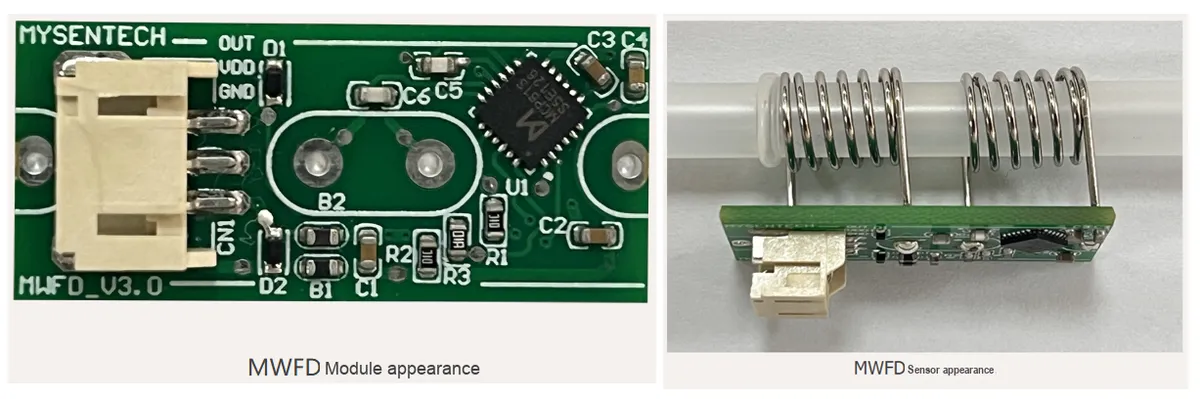
Core Advantages of MWFD: Precise, Fast, and Non-Contact Bubble Detection
- ✅ Non-contact detection completely eliminates contamination and corrosion: MWFD adopts high-frequency capacitance detection technology, which does not require direct contact with the liquid inside the pipeline, fundamentally avoiding the problem of electrode contamination and corrosion; the detector can penetrate non-metallic pipe walls such as plastic and silicone for detection without damaging the pipeline structure, featuring easy installation and compatibility with pipelines of different materials.
- ✅ Strong penetration + high anti-interference, delivering stable performance even in complex scenarios: The sensor features excellent penetration capability, which can effectively address issues such as varying pipe materials, thick pipe walls, and differences in electrical conductivity of different liquids. Equipped with a built-in microprocessor and intelligent algorithms, it supports parameter calibration, temperature compensation, and alarm threshold configuration, effectively filtering out environmental interference, stably distinguishing air from liquid inside pipes, and remains unaffected by water quality or liquid composition.
- ✅ Ultra-fast response speed for real-time device security protection: The measurement response speed reaches up to a 20ms detection cycle. Combined with the microprocessor algorithm, it can quickly distinguish the state inside the pipeline within 500ms. When air/bubbles are detected, it outputs a high-level alarm signal to promptly trigger flow cut-off protection, avoiding risks such as dry heating and idling of the equipment, and safeguarding the safe operation of the equipment.
- ✅ Multi-diameter compatibility + easy integration, suitable for various scenarios: The detector offers multiple spring inner diameter specifications, compatible with pipes of different diameters ranging from 3.5mm to 12.5mm; featuring a compact module structure for easy installation, it supports quick integration into various fluid delivery equipment, making it an ideal bubble detection solution for water dispensers, coffee machines, medical devices and industrial fluid systems.
Can be used for:
- Small Home Appliance Scenarios: Flow Interruption and Air Bubble Protection for Water Dispensers and Coffee Makers: In devices such as water dispensers and coffee makers, the MWFD can be installed on the water delivery pipeline to detect air bubbles and flow interruptions in the water flow in real time. When air bubbles or flow interruption occurs in the pipeline, the detector can quickly identify the abnormality and output a signal to trigger the device's anti-dry-burning protection, preventing the heating tube from being damaged due to idling without water; its non-contact design will not be contaminated by scale, and it can maintain stable detection performance even after long-term use, providing reliable safety protection for the equipment.
- Medical Device Scenario: Bubble Monitoring for Infusion/Fluid Delivery: In medical infusion devices, MWFD can be installed on the infusion line to non-invasively detect bubbles inside the pipeline, preventing potential safety hazards caused by bubbles entering the human body. The detector is compatible with infusion tubes of different diameters, does not come into contact with the medical solution and thus will not contaminate it. Meanwhile, its fast response speed enables timely bubble identification, providing a guarantee for the safe operation of medical devices.
- Industrial Fluid Scenario: Continuous Monitoring of Pipeline Fluid: In industrial fluid delivery systems, MWFD can be used to detect flow interruptions and air bubbles in pipelines, so as to prevent problems such as pump idling and pipeline blockage; the detector is not affected by liquid conductivity or impurities, and can work stably in complex industrial environments, providing reliable data support for the automatic control and safety monitoring of fluid systems.
I. Module Introduction
The MWFD (Minyuan Water Flow Detector), a water flow and air bubble detector, measures changes in the dielectric constant of the liquid inside the pipe via a high-frequency capacitance detection chip: different capacitance values indicate whether the pipe contains air or liquid, and it outputs a high level for alarm once air is detected. Featuring strong penetration, this sensor can effectively address issues such as varying water pipe materials, thick pipe walls, and differences in the conductivity of different liquids. It boasts a fast measurement response, with a maximum detection cycle of 20ms, and can identify the current state within 500ms in coordination with the microprocessor algorithm.The built-in microprocessor chip supports functions such as parameter calibration, temperature compensation, detection algorithm and alarm threshold configuration.
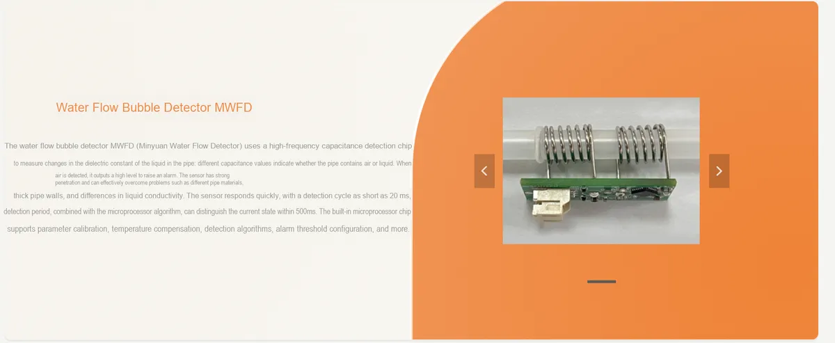
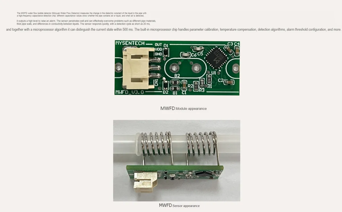
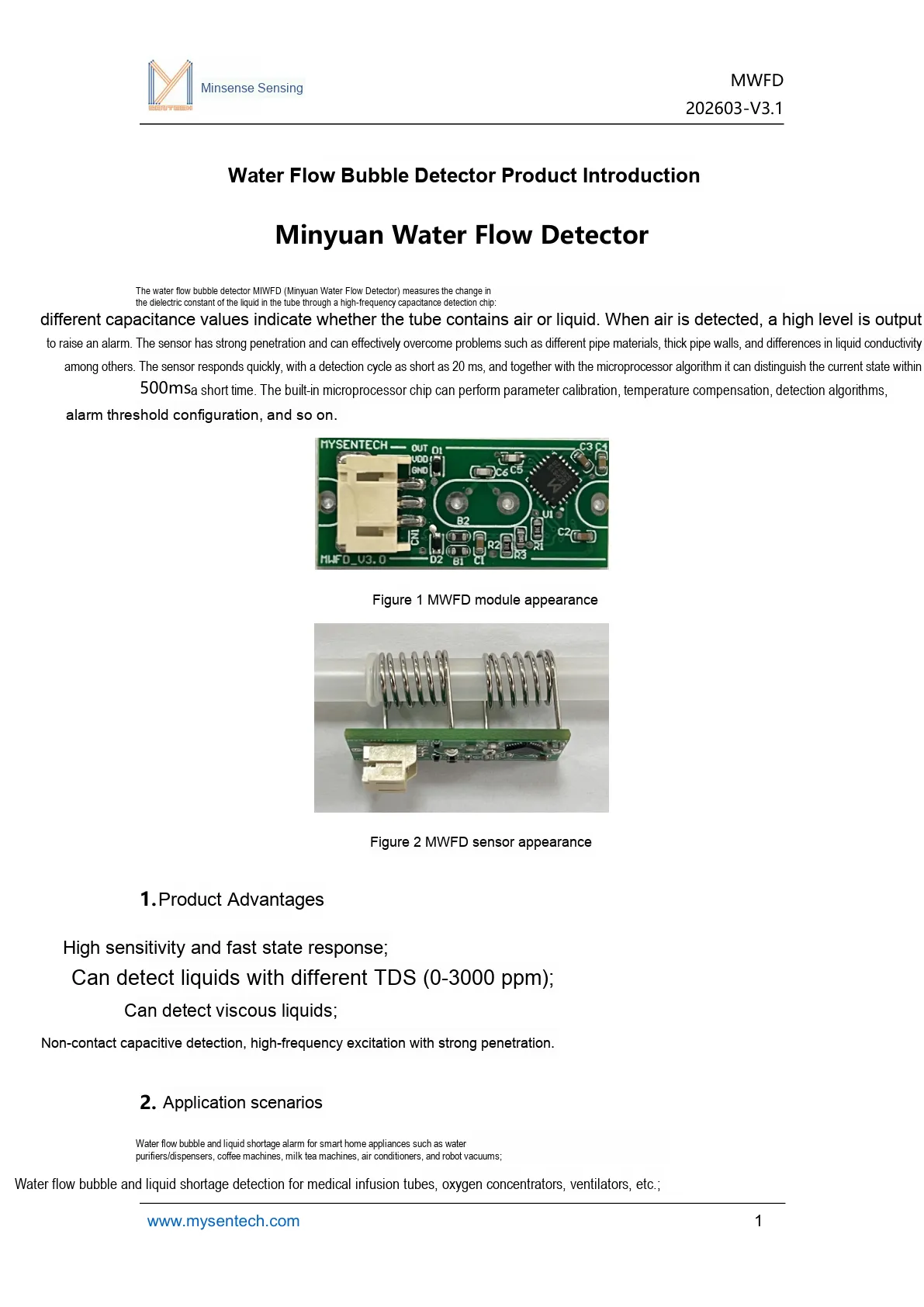
This figure presents the product introduction, module appearance and main application scenarios of MWFD.
- It detects the change in the dielectric constant inside the tube via a high-frequency capacitor to distinguish between air and liquid states.
- Output a high-level alarm when air, bubbles, or insufficient liquid is detected;
- It features strong penetration and is adaptable to scenarios involving different pipe materials, thick pipe walls, and varying liquid conductivity.
- Suitable for scenarios such as water purifiers, coffee machines, milk tea machines, infusion lines, and liquid pumping by water pumps.
2. Introduction to Main Chips
2.1 Chip Overview
The module operates entirely based on the high-frequency capacitance detection principle, identifies water flow, air bubbles and liquid shortage states by measuring the change in the dielectric constant inside the tube, and outputs corresponding digital level signals.
2.2 Pin Definition
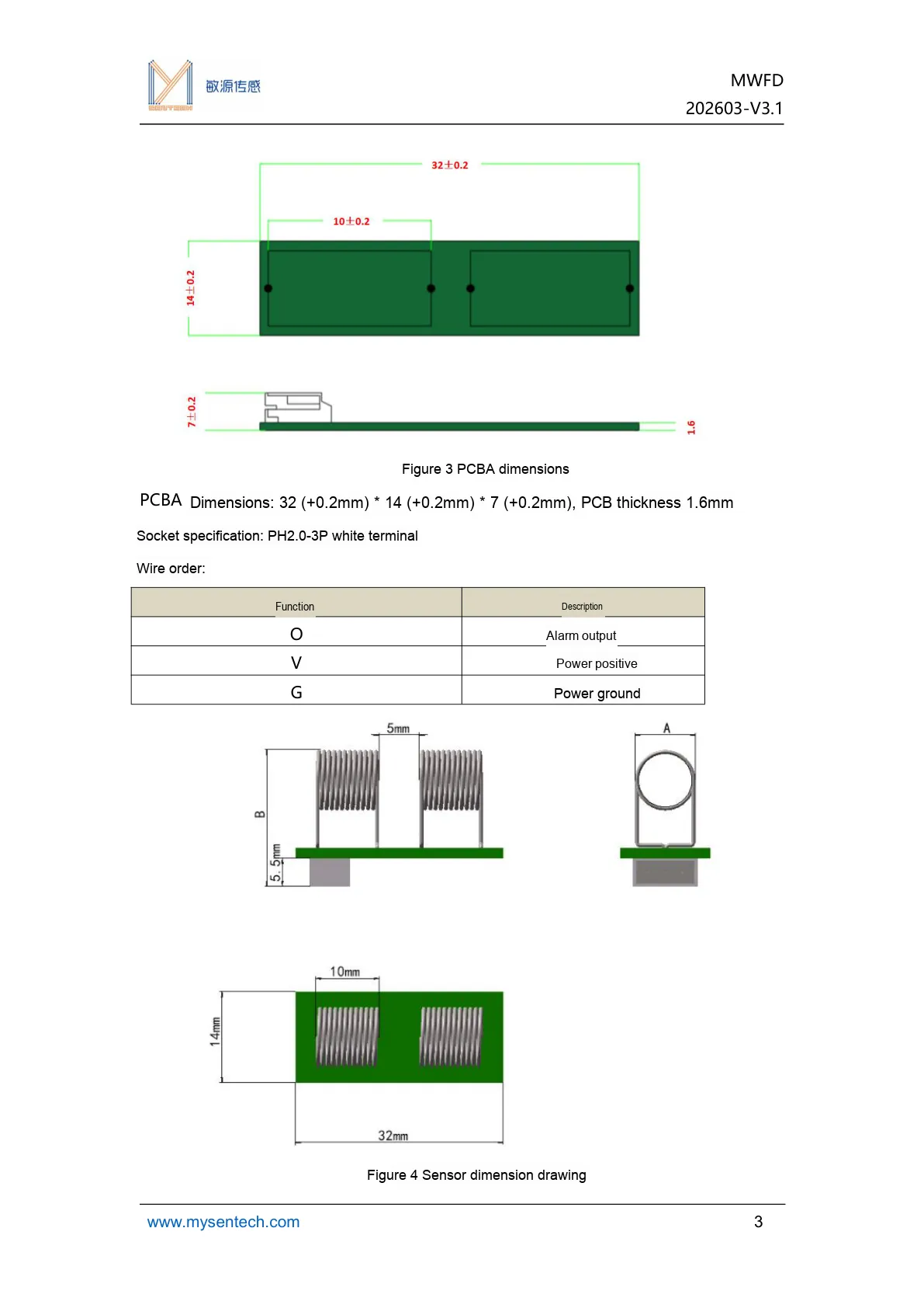
This figure provides the dimensions, interface definitions and wire sequence description of the MWFD, which can be used for hardware integration design.
2.3 Functional Block Diagram
None.
2.4 Performance Parameters
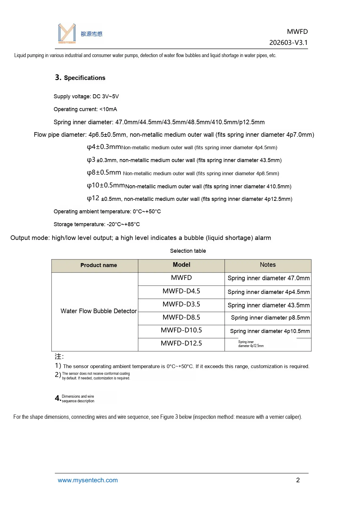
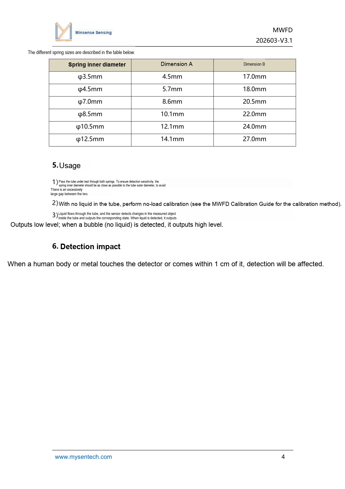
This diagram supplements the dimensional and structural parameters of the sensor spring, serving as a suitable reference for model selection and mechanical mating.
2.5 Reference Circuit
None.
2.6 Chip Configuration
None.
2.7 Communication Interfaces and Related Protocols
This module adopts DIO high and low level output, and does not involve serial Communication Protocols such as UART / I2C / SPI. A high level output indicates a detected bubble or liquid shortage alarm, while a low level output indicates a normal liquid state.
III. Circuit Engineering
3.1 Circuit Source Engineering
To obtain the source project of the circuit, please refer to the link below:
https://mysentech.com/productinfo/2423155.html
3.2 Module Usage Instructions
3.2.1 Module Test Environment Setup and Notes
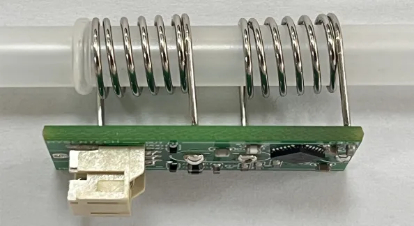
Pass the pipeline under test through both spring electrodes of the module simultaneously; to ensure detection sensitivity, the following requirements must be met:
- The inner diameter of the spring should be matched with the outer diameter of the pipeline as much as possible to avoid an excessive gap between them, as an excessively large gap will reduce the detection accuracy.
- The spring electrode must not directly come into contact with conductive objects such as desktops and metals to avoid introducing interference.
- During installation, avoid relative displacement between the pipeline and the spring to reduce detection fluctuations caused by mechanical vibration.
The module supports connections for two usage scenarios:
- Development Board Debugging: Connect the MWFD to the
3-pin socket of the MCSK-MWFDcalibration development board; the development board is connected to the PC via USB for calibration and data debugging. - Main Control Integration: The module can be directly connected to the user's main control IO port, and the detection status is judged by the output level. Core interface definition:
| Pin | Function description |
|---|---|
| OUT | Signal output: low level = liquid present (normal), high level = bubble / no liquid |
| VCC/GND | Power and ground pins; must match the module's rated voltage |
When using the device for the first time, replacing the pipeline/liquid, or detecting a deviation, it is necessary to perform no-load calibration to eliminate system errors. The steps are as follows:
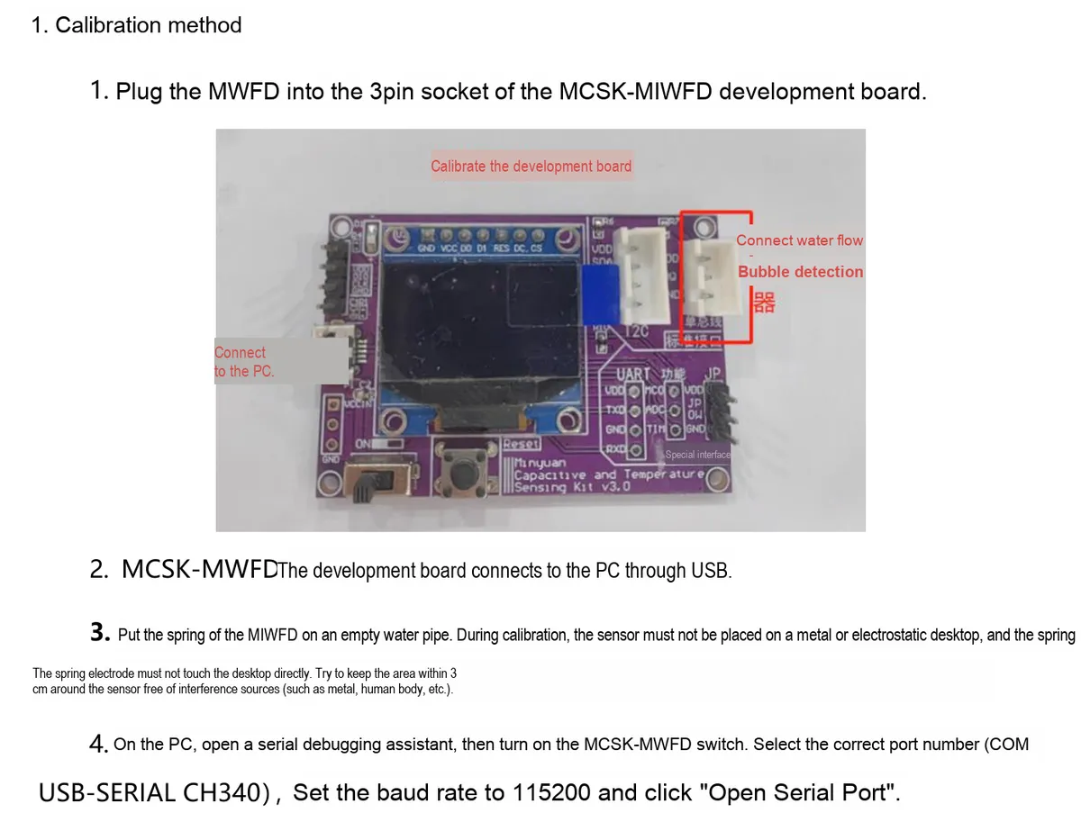
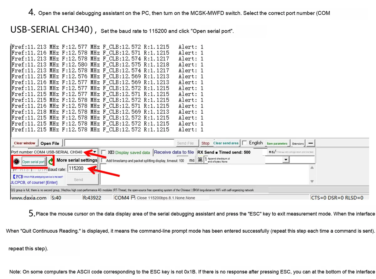
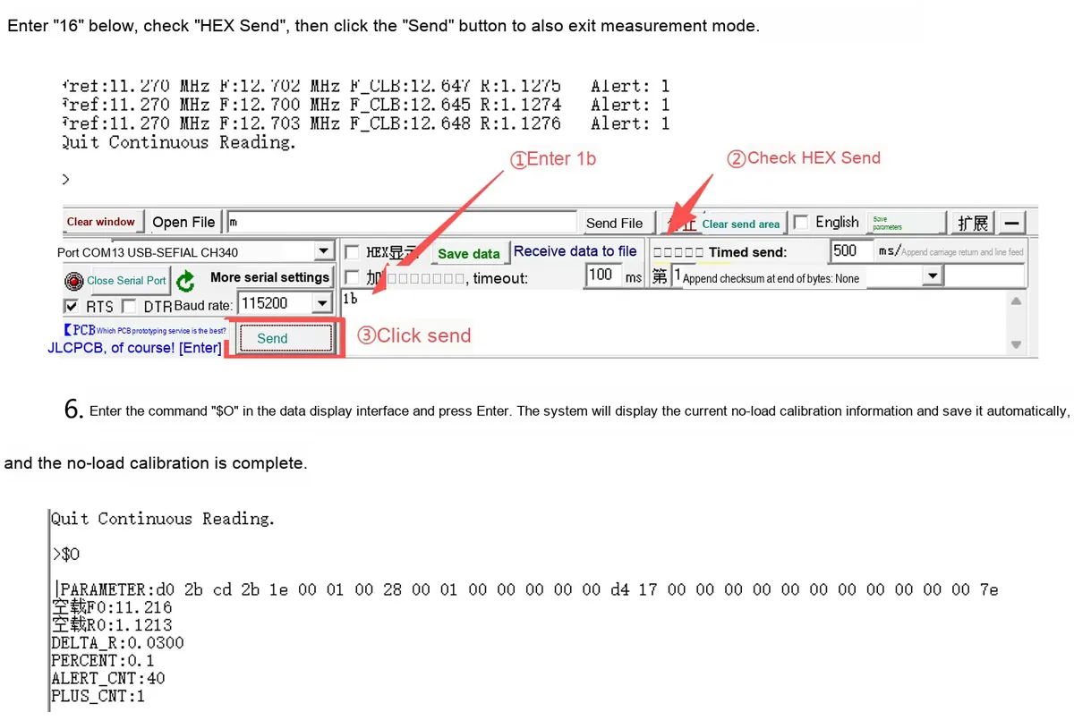
After completing the no-load calibration, refer to the content in the following section to enter the normal operation mode.
When using it, the following points should also be noted:
- Interference Source Protection: When a human body or a metal object touches or approaches the sensor within 1 cm, it will interfere with the capacitance detection and cause misjudgment, so sufficient interference-free space shall be reserved during installation.
- Calibration and Maintenance: When replacing the pipeline, changing the liquid type, or when there is a significant change in the detection environment (temperature, humidity), re-execution of no-load calibration is required to ensure detection accuracy.
- Installation Stability: The spring and the pipeline must be kept in a fitted state to avoid loosening or displacement during long-term use, which may affect the detection sensitivity.
- Environmental Adaptation: Avoid using the module in environments with high temperature or strong electromagnetic interference, so as to prevent the high-frequency detection signal from being affected and resulting in detection anomalies.
Troubleshooting Common Issues:
| Symptom | Troubleshooting steps |
|---|---|
| Unstable detection results / false detections | 1. Check how well the spring fits the tubing and eliminate any gap; 2. Confirm there is no metal or human-body interference around the sensor; 3. Perform no-load calibration again |
| No output signal | 1. Check that the power connection is normal; 2. Confirm the IO pin wiring is correct; 3. Restart the module and recalibrate |
| False bubble alarms during liquid detection | 1. Confirm there are no actual bubbles in the liquid; 2. Check whether the tubing is vibrating or shaking; 3. Recalibrate and optimize the installation position |
3.2.2 Usage of Modbus Poll
Modbus Poll is a universal Modbus master debugging tool compatible with all capacitive sensors in this series that support the Modbus-RTU protocol. It enables quick serial communication debugging, real-time data reading and log export between sensors and computers, serving as a universal host computer tool for verifying sensor functions and collecting test data. The software supports Modbus RTU/ASCII/TCP/IP protocols, is compatible with multiple register types and data formats, and its operation process is universal for the entire series of sensors.
Before use, you need to complete the software installation and activation first. You can download the installation package through official channels; the first launch supports a 30-day trial, and you can also enter a registration code for permanent activation. After the hardware connects the sensor to the computer, open the software and click "Connection" - "Connect", then configure the serial port parameters (Port Number, baud rate, data bit/parity bit/stop bit; this series of sensors defaults to the 9600 Baud, 8N1 format, subject to the specification sheet of the corresponding specific model) in the pop-up window, and confirm to establish a communication connection.
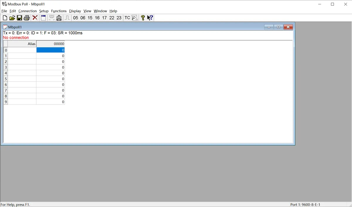
The following is a description of the general operation process:
- Serial Port Connection Configuration: After connecting the sensor to the computer via a USB-to-serial port module, launch the Modbus Poll software, click "Connection" - "Connect" on the menu bar, select the COM Port Number corresponding to the sensor in the pop-up window, and configure the serial port parameters matching the sensor (baud rate, data bits, parity check mode, stop bits; this series of sensors defaults to 9600 Baud, 8N1 format), then confirm to establish a communication connection.
- Import Sensor Configuration File: The software supports importing
. mbppre-configuration files corresponding to various sensor models. These files come with preset register addresses, data formats, and alias definitions, eliminating the need for manual register configuration. Simply open the. mbpfile for the corresponding sensor in the software to automatically load all parameters. Once the connection is established, real-time detection data of the sensor (such as dust/rain/frost thickness values, status flag bits, etc.) will be displayed directly. - Data Logging (Optional): If you need to save test data, you can configure logging rules via the "Setup" - "Excel Log" function. It supports logging data at fixed intervals or with every data update, and allows you to set a maximum number of log entries, facilitating subsequent analysis and verification of sensor data.
The above are the general basic operations of the host computer. For the. mbp preconfiguration files, specific register definitions and special configuration details of different sensor models, please refer to the content in "VII. Related Materials".
3.3 Application Experiment
Here, we use the GraftPort-RP2040 development board for testing, and the water flow bubble detector MWFD uses the DIO interface to communicate with the main controller.
Here, we first use the HY2.0-4P connection cable to connect the module via the PH2.0-3P to Grove adapter board to the GraftPort-RP2040 development board's DIO0 interface:
The module connections are shown in the following table:
Development Board Pins | Module Pins | Description |
Pin 16 |
|
|
GND |
| ground wire |
VCC |
| Power cable, PH2.0-3P to Grove adapter board with 5V to 3.3V circuit, The water flow bubble detector MWFD requires a 3.3V power supply |
Here, we need to search for the relevant driver packages on uPyPI: https://upypi.net/zh/
This diagram demonstrates the procedure for searching for the MWFD driver package in uPyPI.
Enter mwfd_driver to search, and the following will be displayed:
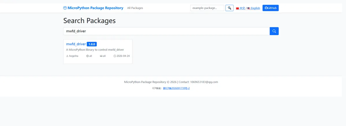
This figure shows the search results for mwfd_driver, which can be used to confirm the driver name.
Click to copy the local installation command:
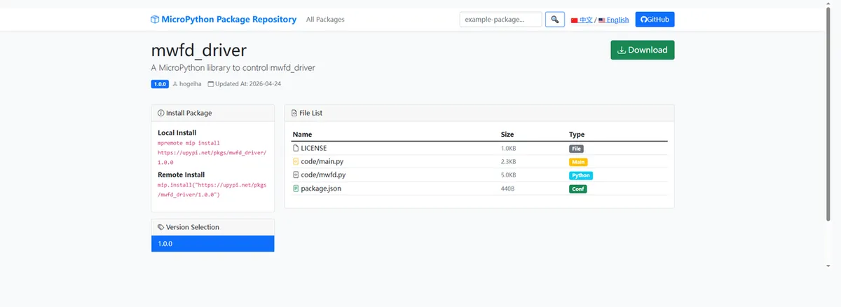
This diagram shows the copy interface of the MWFD driver installation command, which facilitates quick local installation.
Import the module driver library code via the mip tool. Below are the usage commands for the mpremote tool:
mpremote mip install https://upypi.net/pkgs/mwfd_driver/1.0.0Import the MWFD-MicroPython driver code for the water flow bubble detector, then copy the following main.py code into our project:
# Python env   : MicroPython v1.23.0
# -*- coding: utf-8 -*-
# @Time    : 2026/4/3 2:30 PM
# @Author  : hogeiha
# @File    : main.py
# @Description : MWFD water flow bubble detector interrupt and polling example program

# ======================================== Import Modules =========================================
from machine import Pin
from mwfd import MWFD
import time

# ======================================== Global Variables ============================================

# ======================================== Functions ============================================
def on_state_change(state):
    """
    Interrupt callback function, triggered automatically when the sensor state changes
    Args:
        state (bool): True means bubble/no liquid, False means normal liquid

    Raises:
        None

    Notes:
        This function is called by the interrupt service routine and should be kept short and fast

    ==========================================
    Interrupt callback function, automatically triggered when sensor state changes
    Args:
        state (bool): True for bubble/lack of liquid, False for normal liquid

    Raises:
        None

    Notes:
        This function is called by interrupt service routine, keep it short and fast
    """
    # Print different messages according to the state
    if state:
        print("[Interrupt] Warning: Bubble or lack of liquid")
    else:
        print("[Interrupt] Normal liquid")

# ======================================== Custom Classes ============================================

# ======================================== Initialization configuration ===========================================
# Wait 3 seconds for the system to stabilize
time.sleep(3)
# Print the startup banner
print("FreakStudio: MWFD sensor demo started")

# Initialize sensor pin (GPIO15, input mode, internal pull-down)
sensor_pin = Pin(15, Pin.IN, Pin.PULL_DOWN)

# Create MWFD driver instance
sensor = MWFD(sensor_pin)

# Enable interrupt and bind the callback function
sensor.irq(callback=on_state_change)

# ========================================  Main Program  ============================================
# Main loop: actively poll the sensor state and print it
while True:
    # Read current state
    state = sensor.read()
    # Output message according to the state
    if state:
        print("[Polling] Warning: Bubble or lack of liquid")
    else:
        print("[Polling] Normal liquid")
    # Delay 200 ms
    time.sleep(0.2)
Burn the code, open the terminal, and the output is as follows:
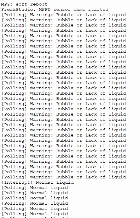
This figure demonstrates the interrupt and polling output effects of the MWFD sample program, through which the feedback of state changes can be visually observed.
4. Drivers
mwfd_driver.zip 4 KB
5. BOM & Recommended Alternative Parts
None
VI. Revision History
Document Version | Date of Modification | Modifier | Revised Content |
v1.0 | 2026-04-24 | Hou Junhan | Initialize Document |
v1.1 | 2026-05-14 | Li Zisheng | Modify the document. |
v1.2 | 2026-05-20 | Li Zisheng | Add introduction and the usage of 3.2.2 Modbus Poll |
VII. Relevant Materials
MWFD Water Flow Bubble Detector Product Manual-MinYuan202603.pdf 564 KB