Contents
- I. Module Introduction
- II. Introduction to Main Chips
- 2.1 Chip Overview
- 2.2 Pin Definition
- 2.3 Functional Block Diagram
- 2.4 Performance Parameters
- 2.5 Reference Circuit
- 2.6 Chip Configuration
- 2.7 Communication Interfaces and Related Protocols
- 2.8 PCB Routing Precautions
- III. Circuit Engineering
- 3.1 Circuit Source Engineering
- 3.2 Module Usage Instructions
- 3.3 Application Experiment
- IV. Drivers
- 5. BOM & Recommended Alternative Parts
- VI. Revision History
- 7. Relevant Materials
- 7.1 Chip Datasheet
- 7.2 Unique Icons for PCB Silk Screen
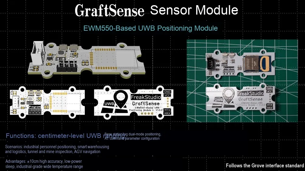
I. Module Introduction
UWB positioning module based on EWM550, which adopts UART serial communication, and is equipped with EWM550-7G9T10SP ultra-wideband wireless ranging chip. It supports the Two-Way Ranging (TWR) algorithm, and can realize two-way ranging for up to 5 targets, with a maximum communication distance of 130 meters (in the CH9 frequency band), a ranging accuracy stably controlled at ±30cm, and a transmission rate of 6.8Mbps. It supports AT command configuration and data transparent transmission, can realize high-precision wireless ranging and positioning, and is suitable for application scenarios such as indoor and outdoor positioning, asset tracking, and robot navigation.
II. Introduction to Main Chips
EWM550-7G9T10SP is a domestic ultra-wideband (UWB) wireless ranging module that supports UART serial communication, adopts the two-way time-of-flight (TWR) algorithm, achieves a ranging accuracy of ±30cm, and has a maximum transmission distance of 130m.
2.1 Chip Overview
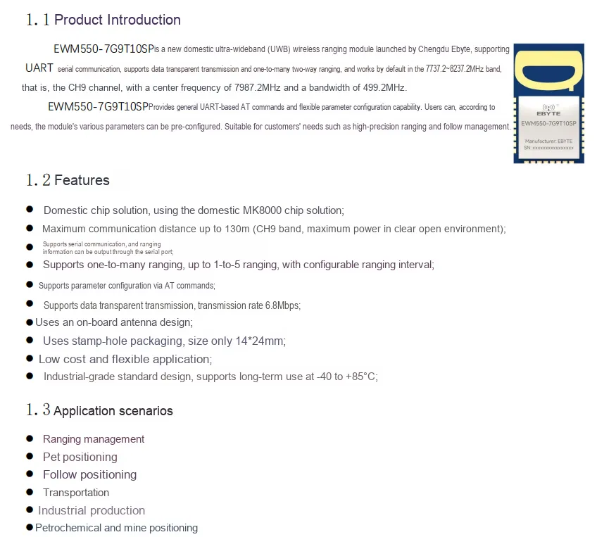
EWM550-7G9T10SP is an ultra-wideband (UWB) wireless ranging module based on the domestic MK8000 chip, featuring an onboard antenna and stamp hole package, supporting UART serial communication and AT command configuration, with a maximum communication distance of 130 meters and a ranging accuracy of ±30cm.
2.2 Pin Definition
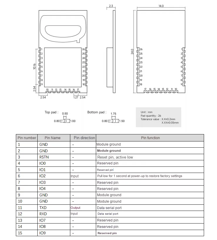
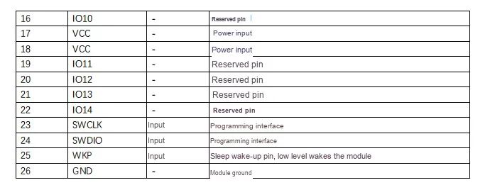
2.3 Functional Block Diagram
None.
2.4 Performance Parameters
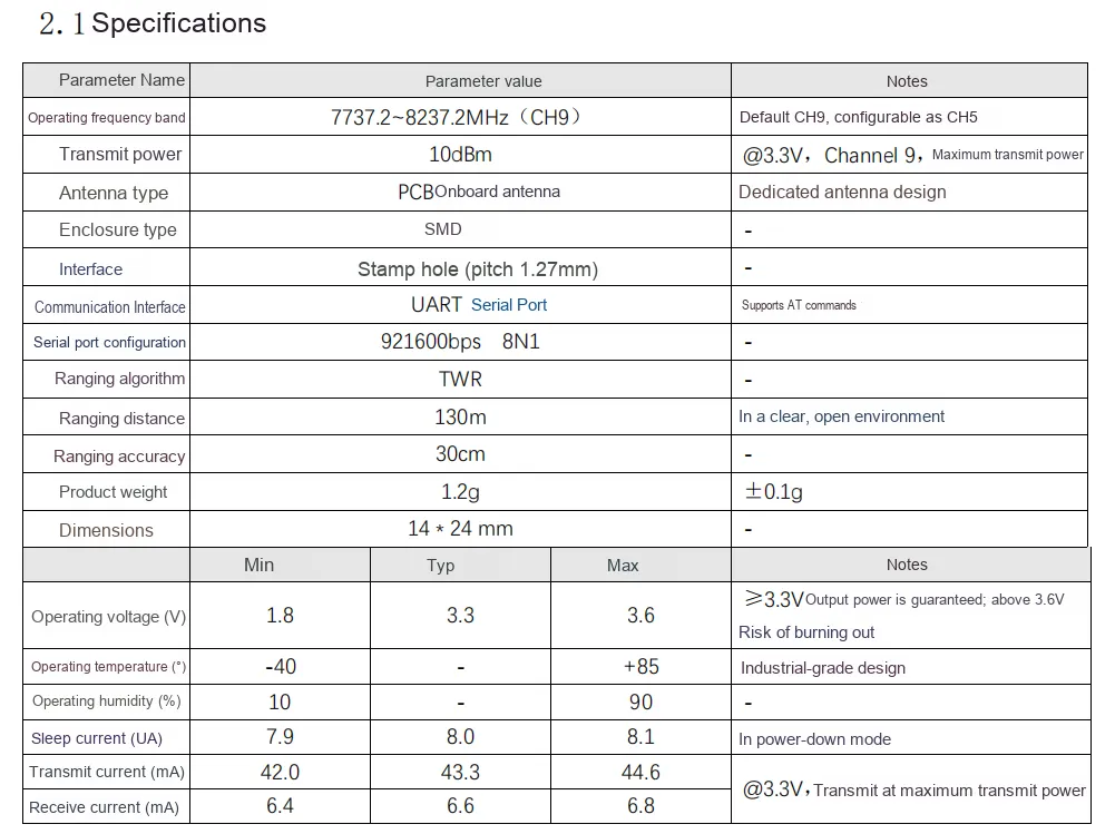
EWM550-7G9T10SP module operates in the 7737.2~8237.2MHz (CH9) frequency band, with a transmit power of 10dBm. It adopts an on-board PCB antenna and a stamp-hole SMD package, measuring only 14×24mm and weighing 1.2g. The communication interface is a UART serial port, with a default baud rate of 921600bps 8N1, and supports AT commands. For ranging, it uses the TWR algorithm, achieving a maximum ranging distance of 130m and a ranging accuracy of ±30cm in open and clear environments.Its operating voltage ranges from 1.8V to 3.6V with a typical value of 3.3V; it features a sleep current as low as 8μA, a transmit current of approximately 43.3mA, a receive current of around 6.6mA, and supports an industrial-grade operating temperature range of -40℃ to + 85℃.
2.5 Reference Circuit
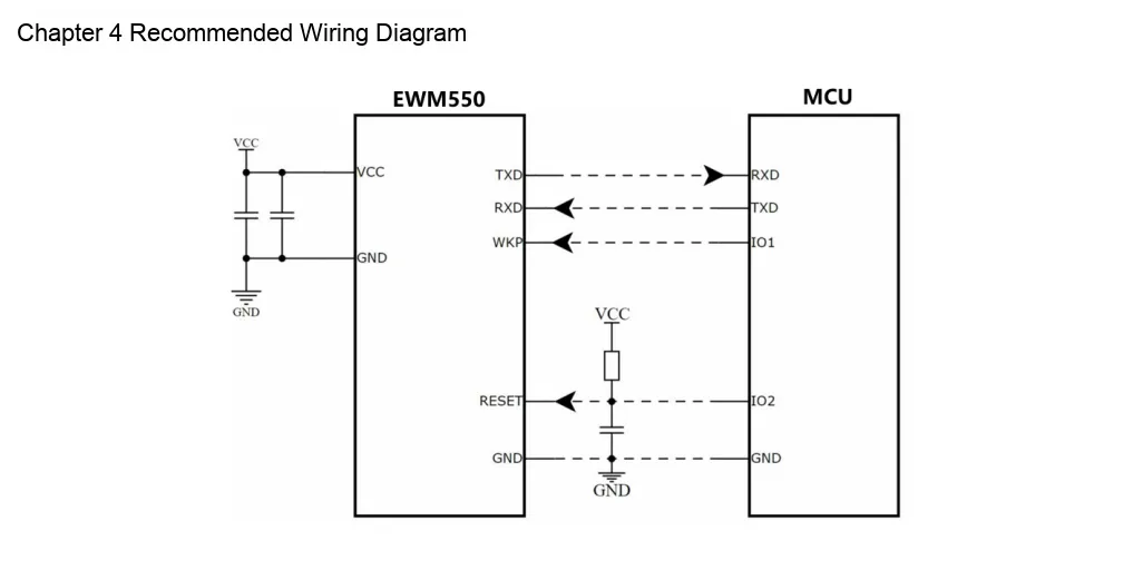
EWM550 module and MCU are connected in the reference circuit as follows: TXD and RXD are cross-connected to implement serial communication, and WKP and RESET are respectively connected to the MCU 's IO pins for wake-up and reset control.
2.6 Chip Configuration
None.
2.7 Communication Interfaces and Related Protocols
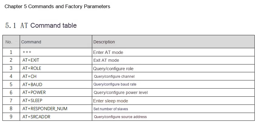

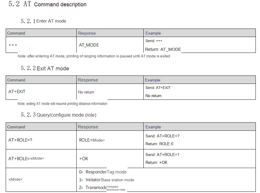
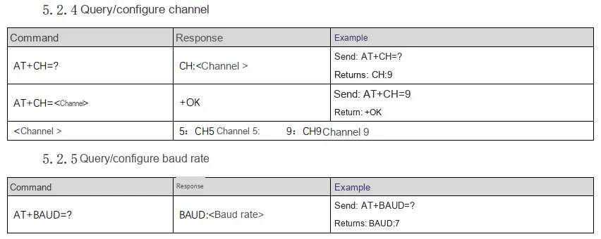
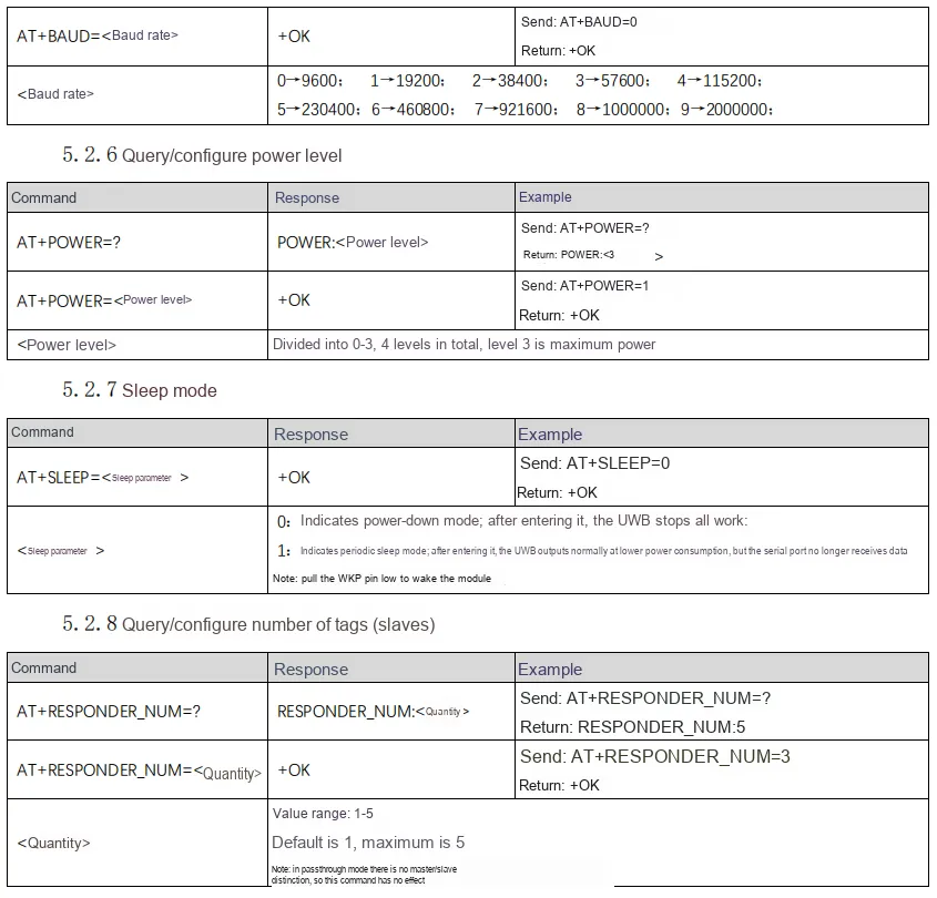
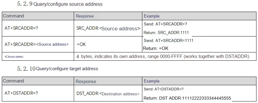
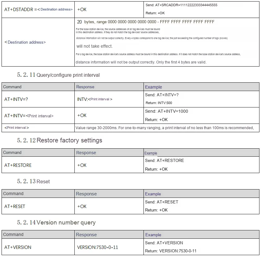
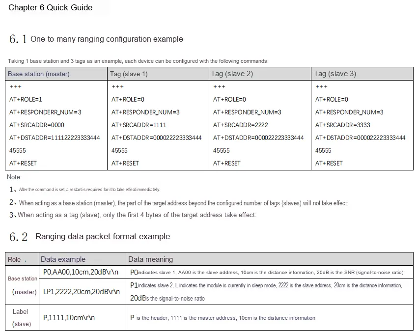
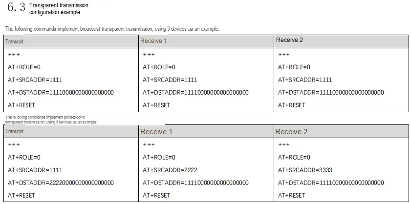

2.8 PCB Routing Precautions
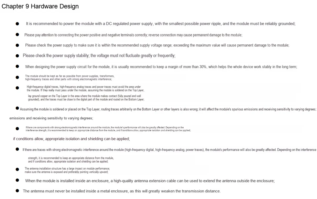
III. Circuit Engineering
3.1 Circuit Source Engineering
To obtain the source code of the circuit, please follow the official account [Freak Embedded]
3.2 Module Usage Instructions
The schematic diagram of this module is shown below:
SCH_EWM550-based UWB positioning module-V1.0.0_2026-03-24.pdf 2.2 MB
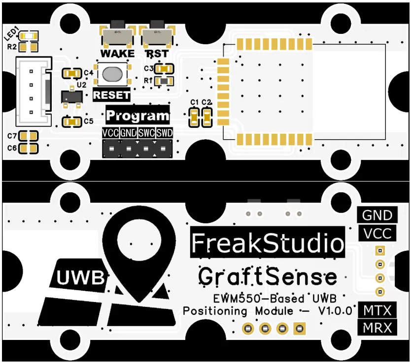
This module provides URAT a communication interface, which can stably implement data interaction and expansion with the main control MCU.
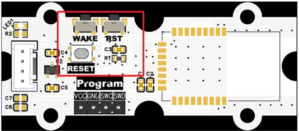
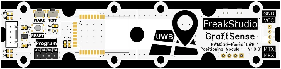
As shown in the figure above, the physical device is equipped with 3 buttons, and the functions of each button are described as follows:
RESET: This button is connected to theIO2pin, and pressing it is used to restore factory settings.RST: Pressing this key is used to reset the system.WAKE: Press this key to wake up the system when it is in sleep state.
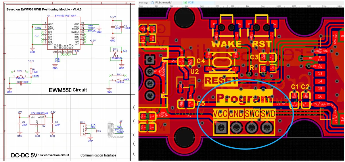
Meanwhile, a 4P interface for upgrading the EWM550-7G9T10SP UWB wireless ranging module is also provided below the module, and users can solder pin headers to perform firmware upgrade when necessary.
It should be noted during use that this module can only measure the distance between the base station and the tag, and cannot measure the distance between tags!!!
3.3 Application Experiment
Here, we use the GraftPort-RP2040 development board for testing, and the UWB positioning module based on EWM550 communicates with the main controller via the UART interface.
Here, we first use the HY2.0-4P cable to connect the module to the GraftPort-RP2040 development board's UART0 and UART1 interfaces:
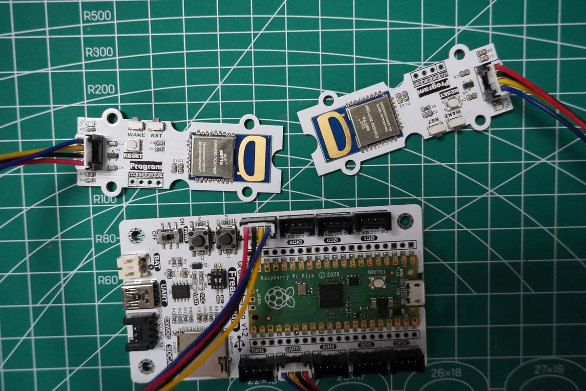
Base Station Side:
Development Board Pins | Module Pins | Description |
Pin 8 |
|
|
Pin 9 |
|
|
Tag side:
Development Board Pins | Module Pins | Description |
Pin 16 |
|
|
Pin 17 |
|
|
When flashing the code, the terminal output is as follows:
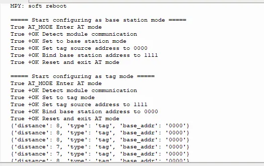
It can be seen that the distance data measured by the UWB module can be correctly read and output to the terminal in real time.
IV. Drivers
ewm550_driver-1.0.1.zip 12 KB
5. BOM & Recommended Alternative Parts
None.
VI. Revision History
Document Version | Date Modified | Modifier | Modify Content |
v1.0 | 2026-03-24 | Ling Gaoxing | Initialize the document |
v1.0.1 | 2026-04-05 | Li Zisheng | The cover photo has not been taken, the production files have not been exported yet, and all other items have been sorted out. |
v1.0.2 | 2026-04-21 | Li Zisheng | The production documents have not been exported yet, and all the rest have been sorted out. |
v1.1 | 2026-04-29 | Xin Ruili | Create an open version of the document based on the internal document version v1.0.2. |
7. Relevant Materials
7.1 Chip Datasheet
EWM550-7G9T10SP_UserManual_CN_V2.0.pdf 1.8 MB
7.2 Unique Icons for PCB Silk Screen