Contents
- I. Module Introduction
- II. Introduction to Main Chips
- 2.1 Chip Overview
- 2.2 Pin Definition
- 2.3 Functional Block Diagram
- 2.4 Performance Parameters
- 2.5 Reference Circuit
- 2.6 Chip Configuration
- 2.7 Communication Interfaces and Related Protocols
- 2.8 PCB Routing Precautions
- III. Circuit Engineering
- 3.1 Circuit Source Engineering
- 3.2 Module Usage Instructions
- 3.3 Application Experiment
- IV. Drivers
- 5. BOM & Recommended Alternative Parts
- VI. Revision History
- 7. Relevant Materials
- 7.1 Chip Datasheet
- 7.2 Unique Icons for PCB Silk Screen
I. Module Introduction
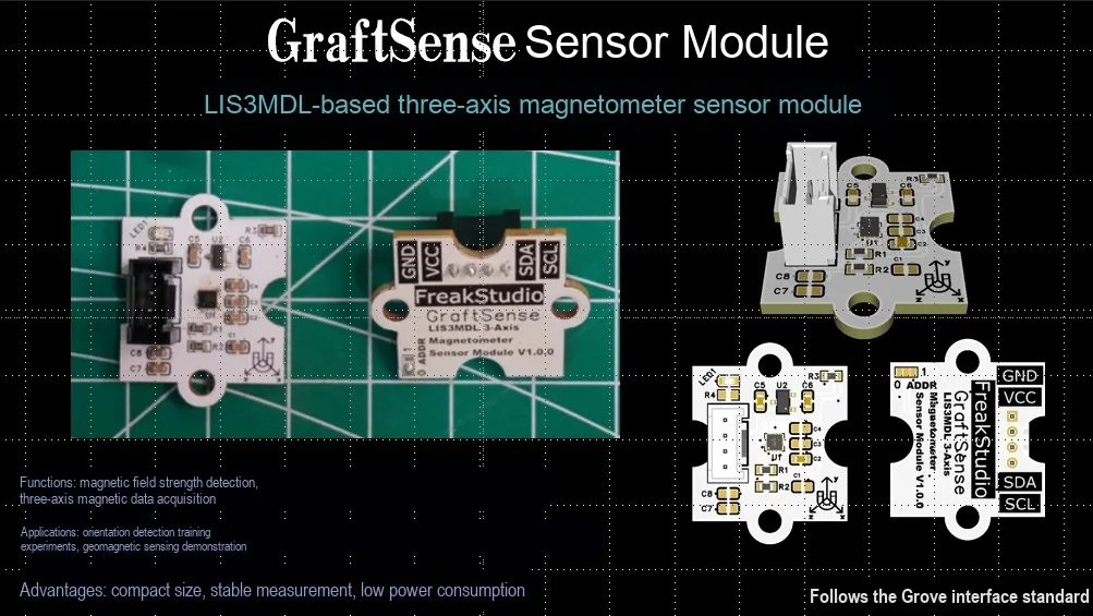
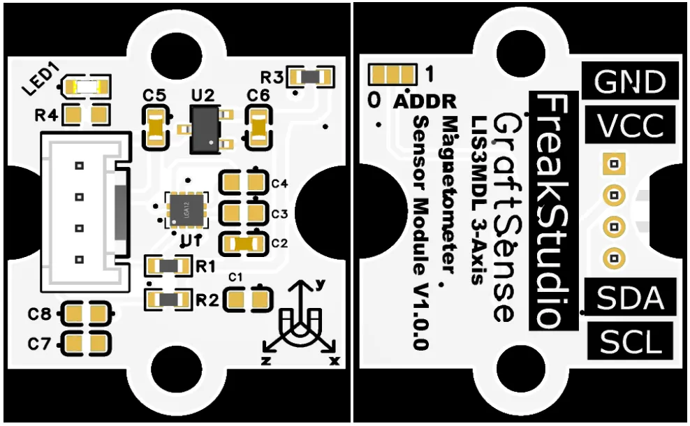
3-axis magnetometer sensor module based on LIS3MDL, which adopts the STMicroelectronics LIS3MDL ultra-low-power 3-axis digital magnetometer solution based on AMR magnetoresistive technology, can accurately measure the magnetic field intensity of the X / Y / Z three axes and output 16-bit digital signals, realizing electronic compass and azimuth calculation;The module is equipped with an address selection circuit, LDO voltage regulator circuit, power filtering and indicator circuit. It is powered by 3.3V and communicates with the main control via the I²C interface. Built-in with temperature compensation and self-calibration functions, it supports programmable interrupt triggering and four-range configuration, and is applicable to scenarios such as drones, wearable devices, navigation and positioning, and AR / VR devices.
II. Introduction to Main Chips
LIS3MDL is a low-power three-axis digital magnetometer launched by STMicroelectronics ( ST ), supporting I ² C / SPI interface, can output three-axis magnetic field data, with temperature compensation, low-power mode and interrupt function, commonly used in electronic compass, position tracking and other scenarios.
2.1 Chip Overview
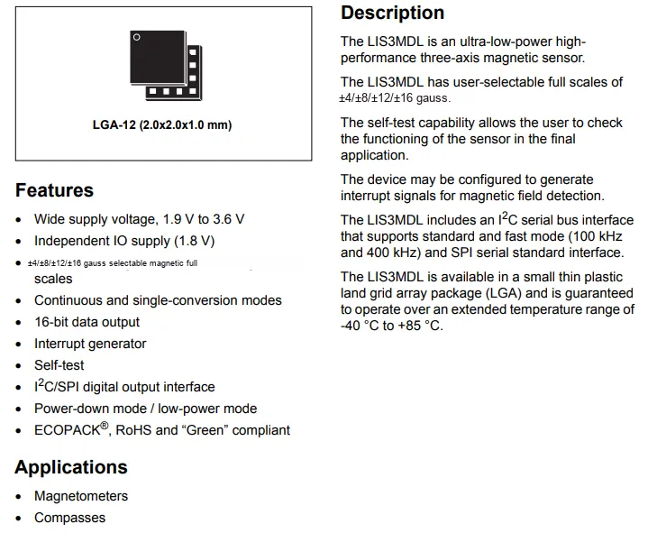
Summarize the content of the picture in a concise paragraph, highlight the key points, and check whether the output is consistent with the picture content.
2.2 Pin Definition
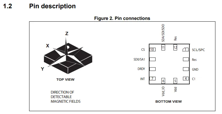
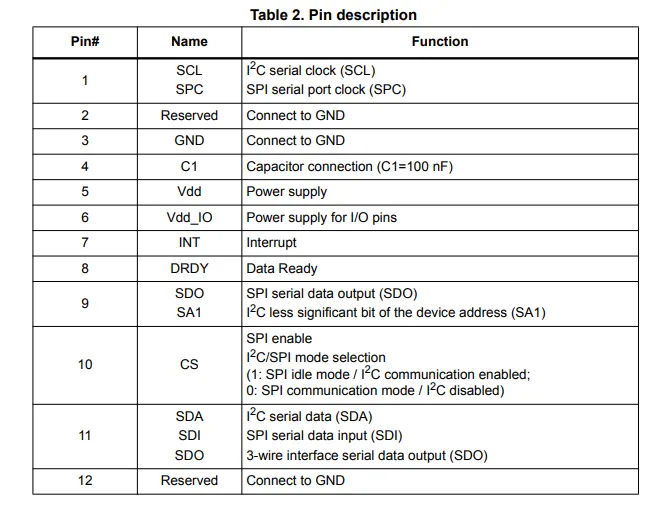
Brief introduction to the pin functions of LIS3MDL, keep it as concise as possible, highlight key points, and check whether the output content is consistent with the content in the picture
2.3 Functional Block Diagram
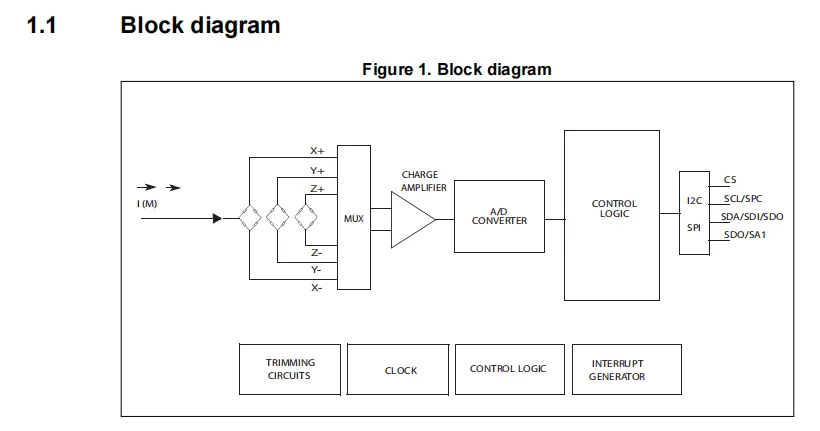
Briefly explain its principle in one paragraph, note: do not use bullet points.
2.4 Performance Parameters
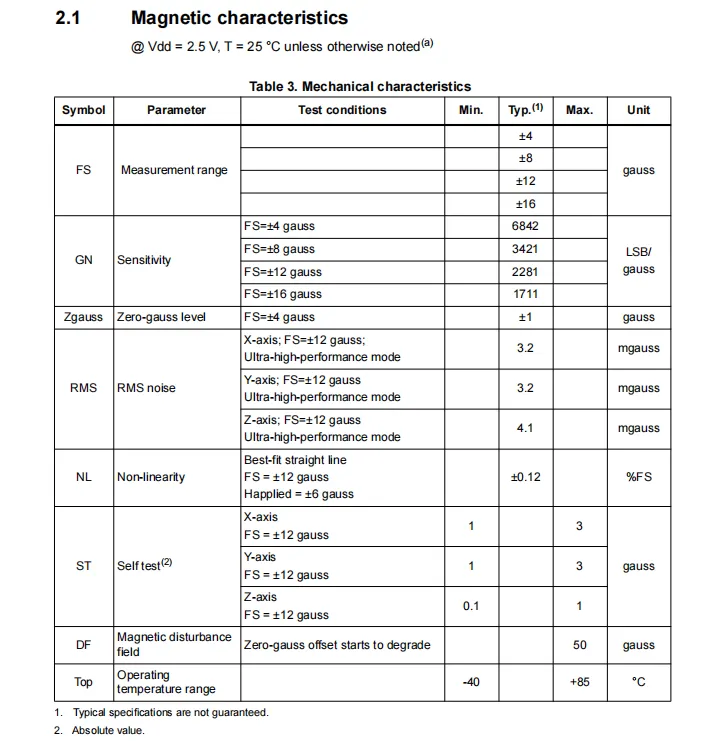
The LIS3MDL operates at a supply voltage of 2.5 V and an ambient temperature of 25 °C, featuring selectable full-scale measurement ranges of ±4, ±8, ±12 and ±16 gauss with corresponding sensitivities (for example, 6842 LSB/gauss at the ±4 gauss range), and also provides key specifications including zero-gauss level, RMS noise, nonlinearity, self-test function and operating temperature range.
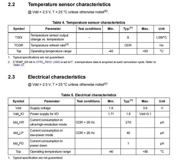
LIS3MDL operates at 2.5V supply and 25°C, with a temperature sensor sensitivity of 8 LSB/°C, and its refresh rate is synchronized with the magnetometer ODR; in terms of electrical parameters, the main supply voltage ranges from 1.9V to 3.6V, the IO supply voltage ranges from 1.71V to Vdd+ 0.1V, the typical power consumption is 270μA in high resolution mode, 40μA in low-power mode, and 1μA in power-down mode, and the operating temperature range is -40°C to + 85°C for all modes.
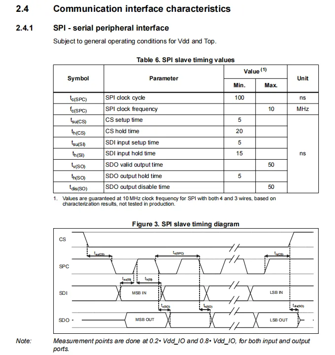
LIS3MDL SPI Sequence Diagram, which specifies that the maximum supported SPI clock frequency is 10MHz (with a period of 100ns), and defines key timing parameters including setup/hold/active/inactive for signals such as CS, SDI, and SDO, to ensure timing compatibility of SPI communication between the master and slave devices.
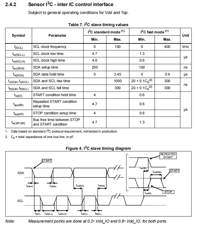
LIS3MDL I²C supports both standard mode (up to 100 kHz) and fast mode (up to 400 kHz), and defines key timing parameters including the high/low voltage levels, setup/hold/rise/fall times, as well as start/repeated start/stop conditions for SCL / SDA, ensuring compatibility with I²C communication timing specifications.
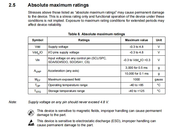
LIS3MDL has an absolute maximum rated power supply and IO voltage range of -0.3V to 4.8V, the upper limit of pin input voltage is Vdd_IO + 0.3V, it can withstand shocks of 3000g (0.5ms) / 10000g (0.1ms), with an upper limit of exposure to magnetic field of 1000 gauss; its operating temperature ranges from -40℃ to + 85℃, and storage temperature ranges from -40℃ to + 125℃. It is also noted that the chip is sensitive to strong magnetic fields and static electricity, and out-of-spec use will cause permanent damage.
2.5 Reference Circuit
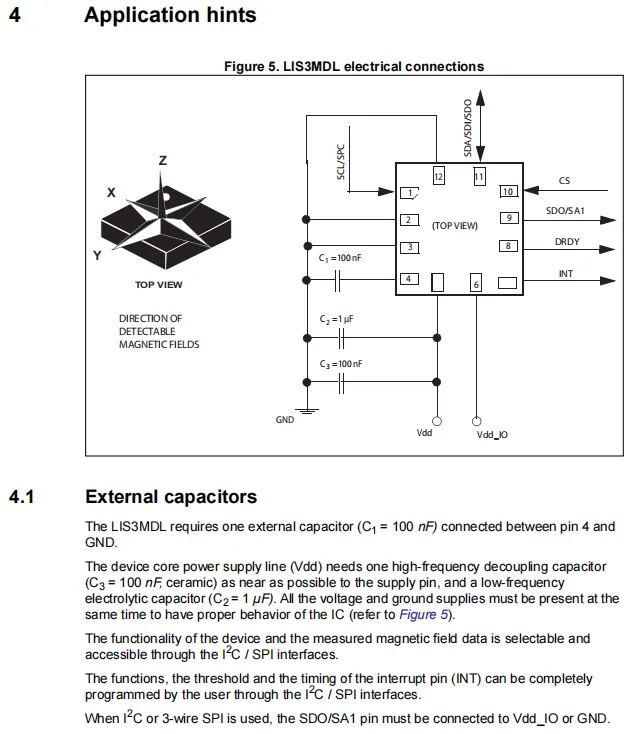
A 1μF low-frequency electrolytic capacitor and a 100nF high-frequency ceramic capacitor are configured at the power supply terminal to filter out power supply noise; an additional 100nF decoupling capacitor is connected to pin 4 to ensure the stability of the internal circuit; the chip communicates with the main controller via the I²C / SPI interface, which can read magnetic field data and configure functions such as interrupt and data ready, and I²C requires a fixed level to avoid floating interference.
2.6 Chip Configuration
None.
2.7 Communication Interfaces and Related Protocols
2.7.1 I2C Communication
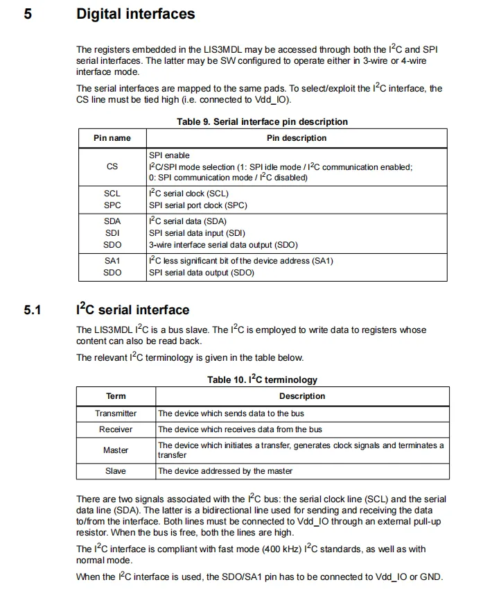
LIS3MDL supports I²C and SPI two serial interfaces which share pins; the CS line is pulled high to select the I²C mode;The I²C interface acts as a slave, compatible with standard / fast mode (max 400kHz), SCL / SDA require external pull-up resistors, and when using I²C, the SDO / SA1 pins must be connected to Vdd_IO or GND.
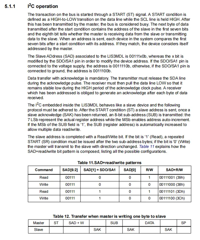
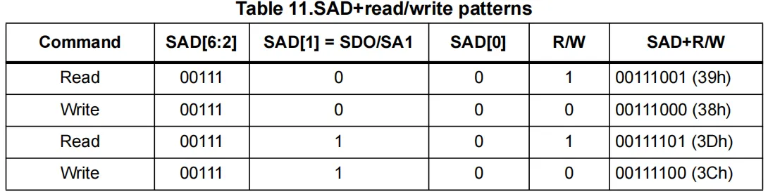
The LIS3MDL chip acts as a slave with a slave address of 00111x0b, where x is determined by the logic level of the SDO / SA1 pin, and read/write commands correspond to different addresses; communication follows the START - Address - Subaddress - Data - STOP sequence. When the most significant bit of the subaddress is 1, automatic address increment is supported, and a slave acknowledge (SAK) is required after each byte transmission.
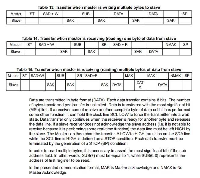
LIS3MDL: When writing multiple bytes, the master device sends a start signal, the slave write address, and the subaddress, then continuously transmits multiple bytes of data and receives the slave's acknowledgment; when reading single/multiple bytes, the subaddress must be written first before sending a repeated start signal and the slave read address. During multi-byte reading, the master device sends an acknowledgment signal (MAK), and finally terminates the transmission with a non-acknowledgment (NMAK); all data is transmitted byte by byte with the most significant bit first. For multi-byte reading, the highest bit of the subaddress must be set to 1 to enable automatic address increment.
2.7.2 Registers
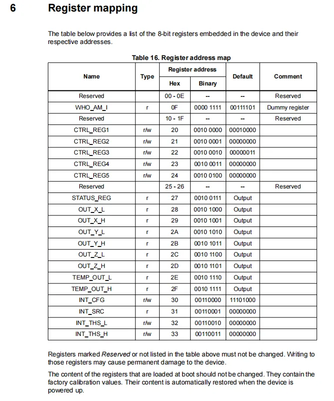
LIS3MDL register address mapping table lists the 8-bit registers ranging from 00h to 33h, including read-only device identification register (WHO_AM_I, address 0Fh), status/data output registers (such as STATUS_REG, OUT_X / Y / Z_L / H, TEMP_OUT_L / H), as well as read-write control registers (CTRL_REG1-5) and interrupt configuration registers (INT_CFG / INT_SRC / INT_THS_L / H), and clearly specifies that reserved registers must not be written to so as to prevent device damage.
2.7.2.1 WHO_AM_I Device Identification Register
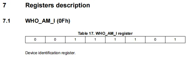
LIS3MDL 's WHO_AM_I (0Fh) device identification register is a read-only register with a fixed value of 00111101 (hexadecimal 3Dh), which is used to verify whether the chip model and communication link are normal.
2.7.2.2 CTRL_REG1 Control Register
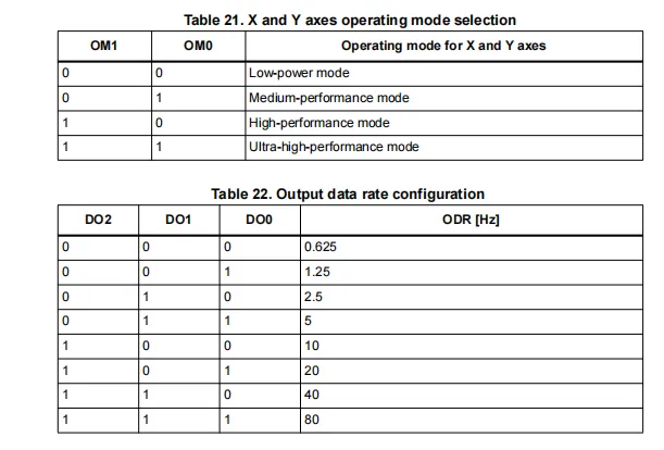
LIS3MDL 's CTRL_REG1 (20h) control register is used to configure the core functions of the sensor: it enables the temperature sensor (TEMP_EN), sets the operating mode of the X / Y axes (OM[1:0], low-power / medium / high / ultra-high performance), configures the output data rate (DO[2:0], 0.625-80Hz, up to 1000Hz when FAST_ODR is set to 1), and also supports the self-test function (ST); it is the core configuration register for the chip' s operating mode.
2.7.2.3 CTRL_REG2 Control Register
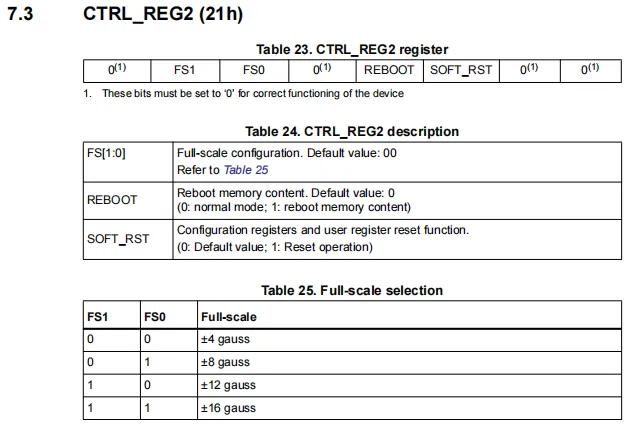
LIS3MDL 's CTRL_REG2 (21h) control register is used to configure the measurement range and reset function: the four magnetic field measurement ranges of ±4/±8/±12/±16 gauss can be selected via FS[1:0], and it also supports the memory reboot (REBOOT) and software reset (SOFT_RST) functions; the remaining reserved bits must be fixed at 0 to ensure normal operation of the chip.
2.7.2.4 CTRL_REG3 Control Register
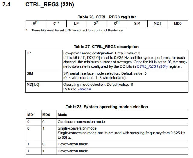
LIS3MDL 's CTRL_REG3 (22h) control register is used to configure low-power, SPI interface and system operating modes: the LP bit forces entry into low-power mode (fixed 0.625Hz sampling), the SIM bit selects the SPI as a 4-wire / 3-wire interface, the MD[1:0] bits set continuous conversion, single conversion or power-down mode, and the remaining reserved bits must be fixed to 0.
2.7.2.5 CTRL_REG4 Control Register
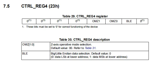
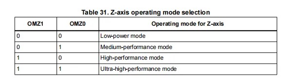
LIS3MDL 's CTRL_REG4 (23h) control register mainly configures Z -axis operating mode and data byte order: the OMZ[1:0] bits can be used to select the Z-axis low-power / medium / high / ultra-high performance mode, the BLE bit sets the data to little-endian (LSB first, default) or big-endian (MSB first) format, and the remaining reserved bits must be fixed to 0.
2.7.2.6 CTRL_REG5 Control Register
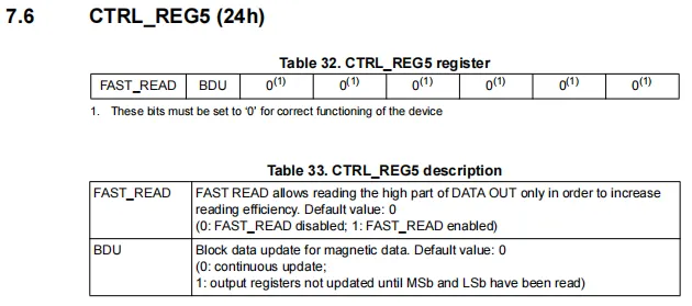
LIS3MDL ’s CTRL_REG5 (24h) control register is used to configure the data read mode: The FAST_READ bit enables a fast read mode that only reads the high byte to improve read efficiency;The BDU bit controls the data update method. When set to 1, the data register remains locked until both the high and low bytes are read to avoid read errors caused by data update, and all other reserved bits must be fixed to 0.
2.7.2.7 STATUS_REG Status Register
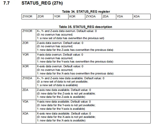
LIS3MDL STATUS_REG (27h) status register is used to feed back the status of three-axis data: the ZYXOR / ZOR / YOR / XOR bits respectively indicate whether the three-axis data has experienced overrun, while the ZYXDA / ZDA / YDA / XDA bits identify whether new data is ready for each axis, making it a key register for judging the timing of data reading and avoiding data loss.
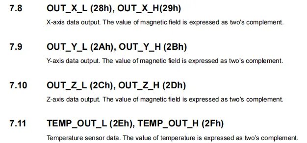
LIS3MDL has three-axis magnetic field data and temperature data registers. The magnetic field values of the X / Y / Z axes are stored in OUT_X / Y / Z_L / H (low/high bytes) respectively, the temperature value is stored in TEMP_OUT_L / H, all data are in 16-bit two's complement format, and the complete value can be obtained by reading and combining the high and low bytes.
2.7.2.8 INT_CFG Interrupt Configuration Register
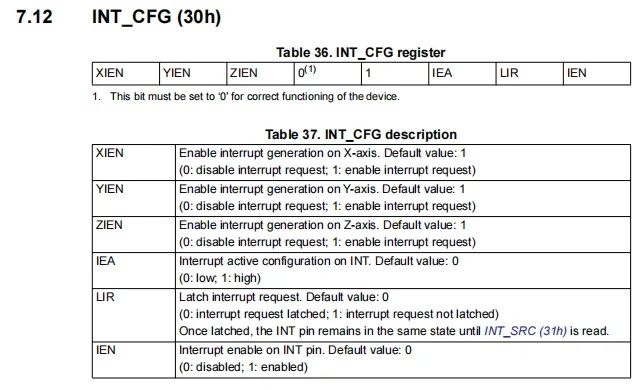
The LIS3MDL 's INT_CFG (30h) interrupt configuration register is used to set the trigger conditions for three-axis magnetic field interrupts: XIEN/YIEN/ZIEN enable interrupts for each axis respectively, IEA configures the interrupt signal polarity (low/high level), LIR sets whether the interrupt is latched (the latched state needs to be cleared by reading INT_SRC), and IEN globally enables the INT pin output. It is the core configuration register for the magnetic field threshold detection function.
2.7.2.9 INT_SRC Interrupt Source Status Register
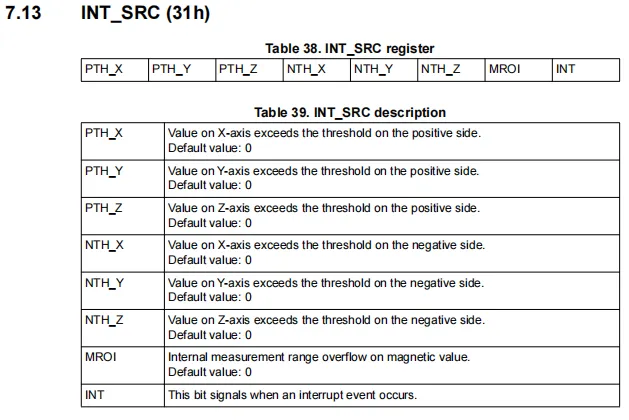
LIS3MDL 's INT_SRC (31h) interrupt source status register is used to feed back the specific cause of interrupt triggering: PTH_X / Y / Z indicates that the magnetic field value of each axis has exceeded the threshold in the positive direction, NTH_X / Y / Z indicates that the magnetic field value has exceeded the threshold in the negative direction, MROI indicates that the measurement range has overflowed, INT bit indicates that any interrupt event has occurred, and reading this register can clear the latched interrupt status.
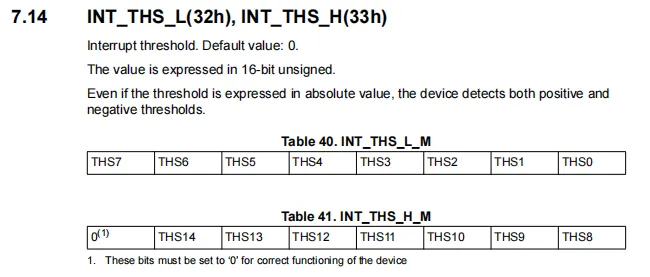
LIS3MDL 's INT_THS_L / H (32h/33h) interrupt threshold register is used to set the trigger threshold for magnetic field interrupts. It consists of the low byte (INT_THS_L) and the high byte (INT_THS_H) to form a 16-bit unsigned number, which defines the threshold in absolute value form and supports the detection of magnetic field over-limit events in both positive and negative directions. The highest bit of the high byte must be fixed to 0 to ensure normal operation of the chip.
2.8 PCB Routing Precautions
None.
III. Circuit Engineering
3.1 Circuit Source Engineering
To obtain the source code of the circuit, please follow the official account [Freak Embedded]
3.2 Module Usage Instructions
The schematic diagram of this module is shown below:
SCH_Schematic1_LIS3MDL-Based Three-Axis Magnetometer Sensor Module_v1.0.0_2026-05-12.pdf 2.1 MB
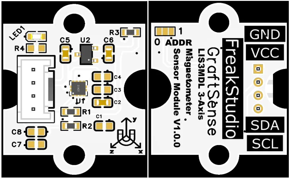
This module provides an IIC / I2C communication rates, allows flexible configuration of the ADDR pin to set the I2C address, is compatible with 3.3V logic levels, and can stably transmit the 16-bit digital signals of triaxial (LIS3MDL -collected) X / Y / Z magnetic field strength. It is applicable to scenarios including drones, wearable devices, navigation and positioning, as well as AR / VR devices, providing the system with reliable data interaction capabilities for electronic compass and orientation sensing.
By setting three short-circuit points to short-circuit ADDR pin network connections, different communication addresses of I2C can be configured:
3.3 Application Experiment
Here, we use the GraftPort-RP2040 development board for testing, and the LIS3MDL-based 3-axis magnetometer sensor module communicates with the main controller via the I2C interface.
Here, we first use the HY2.0-4P connection cable to connect the module to the GraftPort-RP2040 development board's I2C0 interface:
Development Board Pins | Module Pins | Description |
Pin 4 |
|
|
Pin 5 |
|
|
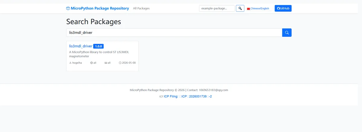
Here, we need to search for the relevant driver packages on uPyPI: https://upypi.net/zh/
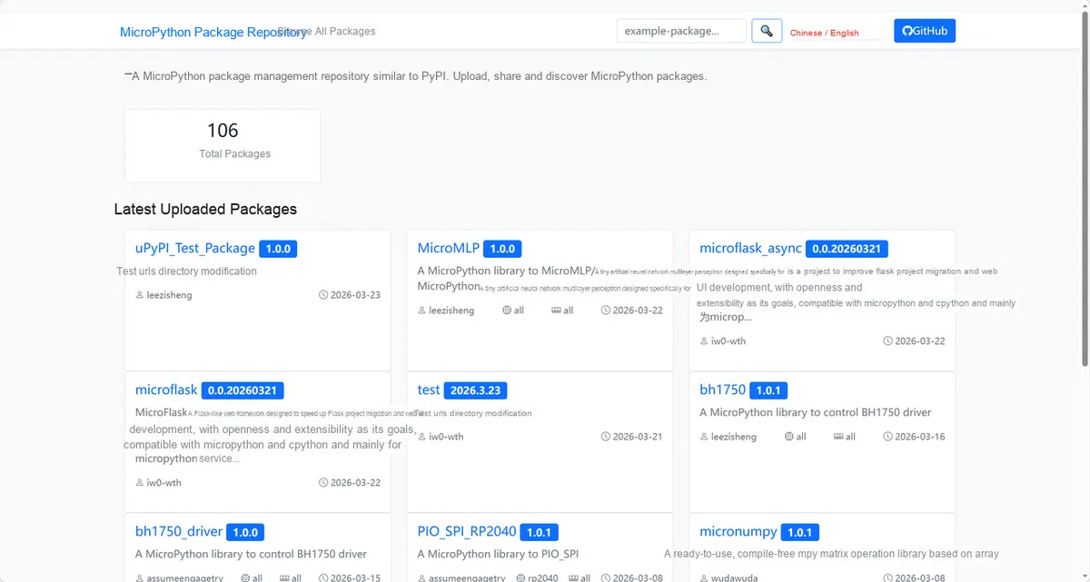
Enter lis3mdl_driver to search, and the following will be displayed:
Click to copy the local installation command:
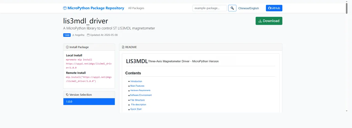
Import the module driver library code via the mip tool. Below are the usage commands for the mpremote tool:
mpremote mip install https://upypi.net/pkgs/lis3mdl_driver/1.0.0Import the MicroPython driver code for the LIS3MDL-based 3-axis magnetometer sensor module, then copy the following main.py code into our project:
# Python env   : MicroPython v1.23.0
# -*- coding: utf-8 -*-
# @Time    : 2025/9/8 4:52 PM
# @Author  : Jose D. Montoya
# @File    : main.py
# @Description : Read and print magnetic field data using the LIS3MDL magnetometer sensor
# @License : MIT
__version__ = "0.1.0"
__author__ = "Jose D. Montoya"
__license__ = "MIT"
__platform__ = "MicroPython v1.23.0"

# ======================================== Import Modules =========================================

import time
from machine import Pin, SoftI2C
from micropython_lis3mdl import lis3mdl

# ======================================== Global Variables ============================================

# List of possible I2C addresses of the target sensor (multiple addresses supported)
TARGET_SENSOR_ADDRS: list[int] = [0x1C, 0x1E]

# SDA pin number used by the I2C bus
I2C_SDA_PIN: int = 4
# SCL pin number used by the I2C bus
I2C_SCL_PIN: int = 5
# I2C bus communication frequency (Hz)
I2C_FREQ: int = 400000

# ======================================== Functions ============================================

# ======================================== Custom Classes ============================================

# ======================================== Initialization configuration ===========================================

time.sleep(3)
print("FreakStudio: LIS3MDL sensor auto scan and data acquisition")
# Create a software I2C bus instance
i2c_bus = SoftI2C(sda=Pin(I2C_SDA_PIN), scl=Pin(I2C_SCL_PIN), freq=I2C_FREQ)

# Scan all device addresses on the I2C bus
devices_list: list[int] = i2c_bus.scan()
print("START I2C SCANNER")

# Check whether any I2C devices were found
if len(devices_list) == 0:
    print("No i2c device !")
    raise SystemExit("I2C scan found no devices, program exited")
else:
    print("i2c devices found:", len(devices_list))

# Placeholder for the sensor object
sensor: lis3mdl.LIS3MDL = None

# Iterate through the scanned device addresses to match the target address
for device in devices_list:
    if device in TARGET_SENSOR_ADDRS:
        print("I2c hexadecimal address:", hex(device))
        try:
            # Create the LIS3MDL sensor object
            sensor = lis3mdl.LIS3MDL(i2c=i2c_bus)
            print("Sensor initialization successful")
            break
        except Exception as e:
            print(f"Sensor Initialization failed: {e}")
            continue
else:
    # No target sensor address found on the bus
    raise Exception("No target sensor device found in I2C bus")

# ========================================  Main Program  ============================================

# Main loop: read and print magnetic field data every 0.5 seconds
while True:
    mag_x, mag_y, mag_z = sensor.magnetic
    print(f"X:{mag_x:0.2f}, Y:{mag_y:0.2f}, Z:{mag_z:0.2f} uT")
    print("")
    time.sleep(0.5)
Burn the code, open the terminal, and the output is as follows:
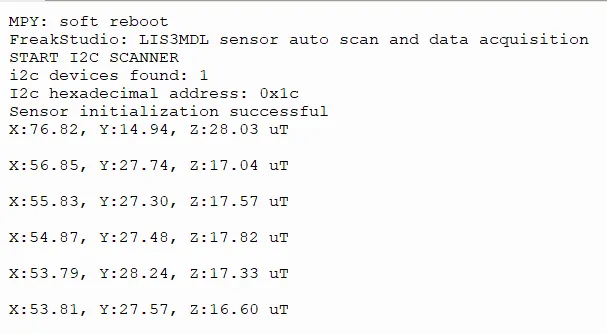
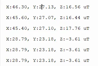
The LIS3MDL geomagnetic sensor features normal I2C communication and initialization (address: 0x1c). Its three-axis geomagnetic readings remain stable when stationary, and the X/Y/Z axis values fluctuate in real time with position changes during attitude adjustment, indicating normal operating response.
IV. Drivers
lis3mdl_driver-1.0.0.zip 15 KB
5. BOM & Recommended Alternative Parts
None.
VI. Revision History
Document Version | Date Modified | Modifier | Modify Content |
v1.0 | 2026-05-12 | Ling Gaoxing | Initialize the document |
v1.1 | 2026-06-03 | Xin Ruili | Create an open version of the document based on the internal document version v1.0. |
7. Relevant Materials
7.1 Chip Datasheet
LIS3MDL.pdf 1.6 MB
7.2 Unique Icons for PCB Silk Screen