Contents
- I. Module Introduction
- II. Introduction to Main Chips
- 2.1 Chip Overview
- 2.2 Pin Definition
- 2.3 Functional Block Diagram
- 2.4 Performance Parameters
- 2.5 Reference Circuit
- 2.6 Chip Configuration
- 2.7 Communication Interfaces and Related Protocols
- 2.8 PCB Routing Notes
- III. Circuit Engineering
- 3.1 Circuit Source Engineering
- 3.2 Module Usage Instructions
- 3.3 Application Experiment
- IV. Drivers
- 5. BOM & Recommended Alternative Parts
- 6. Revision History
- VII. Relevant Materials
- 7.1 Chip Datasheet
- 7.2 Unique Icons for PCB Silk Screen
I. Module Introduction
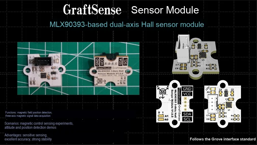
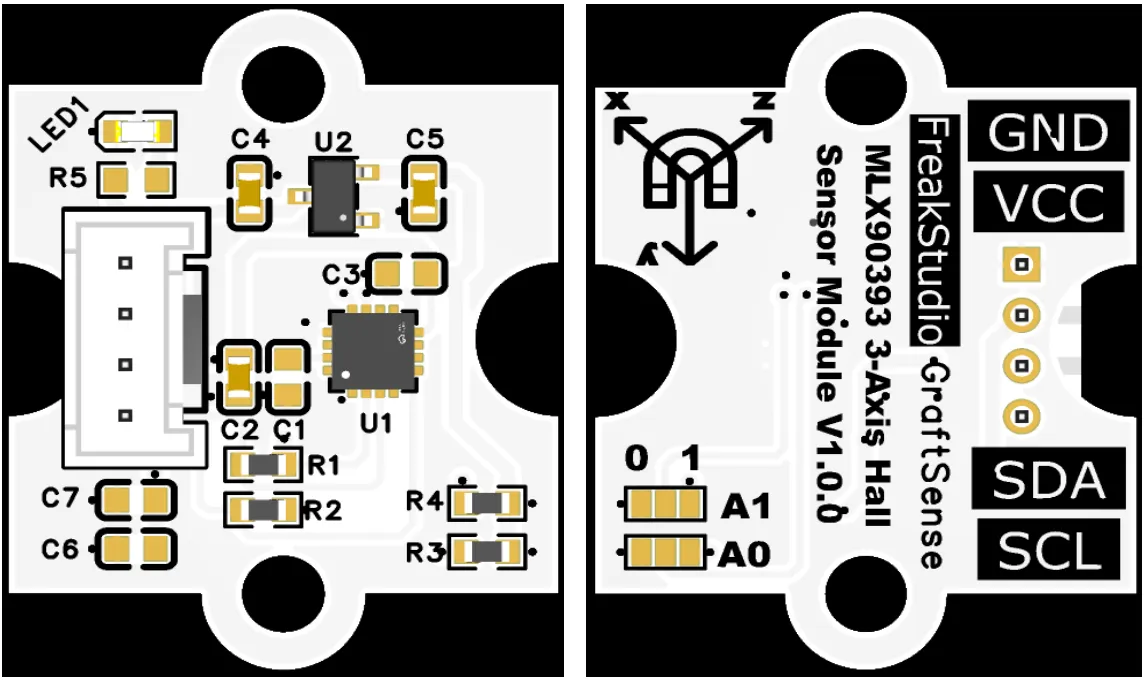
3-axis Hall sensor module based on MLX90393, which adopts Melexis MLX90393 3-axis Hall effect magnetic field sensor solution, can accurately measure the magnetic field strength of the X / Y / Z three axes and output a 16-bit digital signal, realizing the detection of 3D position, angle and compass orientation;The module is equipped with an address selection circuit, LDO voltage regulator circuit, power filtering and indicator circuit. It is powered by 3.3V and communicates with the main controller via the I²C interface. It supports four-range configuration and low-power mode, and is suitable for scenarios such as 3D joysticks, , position detection, electronic compasses, and IoT low-power magnetic field sensing devices.
II. Introduction to Main Chips
MLX90393 is a low-power 3-axis Hall-effect magnetic field sensor that adopts Triaxis® technology, outputs 16-bit magnetic field and temperature data of the XYZ axes, supports I²C / SPI interfaces and programmable duty cycle, and comes in a QFN 3×3mm package.
2.1 Chip Overview

MLX90393 3-axis Hall effect magnetic field sensor is based on Triaxis® technology, featuring a wide dynamic range (5–50 mT), programmable gain/duty cycle, I²C / SPI interfaces, on-chip filtering and a temperature sensor. It supports external/internal triggering and magnetic field change interrupts, targeting application scenarios such as contactless position detection for industrial and consumer use cases.
2.2 Pin Definition
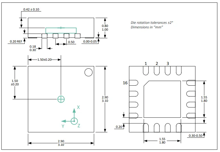
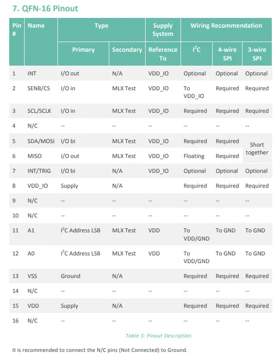
MLX90393 adopts the QFN-16 package, where VDD / VSS serve as power supply/ground, and VDD_IO supplies power for IO; it supports I²C (with SCL / SDA and A0 / A1 for address configuration) and SPI (including SCLK / MOSI / MISO / CS) interfaces. INT / TRIG functions as the interrupt/trigger pin, and the remaining pins are NC pins which are recommended to be grounded.
2.3 Functional Block Diagram
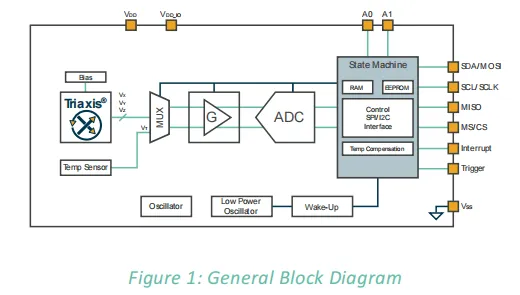
MLX90393 is based on Triaxis® Hall sensing technology. It acquires three-axis magnetic field and on-chip temperature signals via a multiplexer; after programmable gain amplification and analog-to-digital conversion, a finite-state machine completes data processing and temperature compensation, and finally outputs digital signals through the I²C / SPI interface. Meanwhile, it integrates a low-power oscillator and wake-up module, supports interrupt and external triggering, and enables flexible power consumption and performance control.
2.4 Performance Parameters
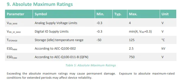
MLX90393 chip has an absolute maximum analog supply voltage (VDD) range of -0.3 V to 4 V, the upper limit of its digital IO supply (VDD_IO) is min (4 V, VDD + 0.3 V), the storage temperature ranges from -50 ℃ to 125 ℃, it withstands 2.5 kV for HBM ESD and 750 V for CDM ESD; exceeding these parameters may result in permanent chip damage or reduced reliability.
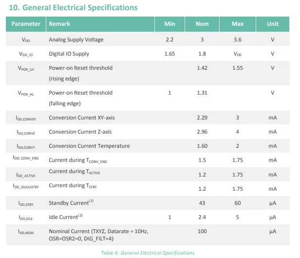
MLX90393 has an operating analog supply voltage (VDD) range of 2.2–3.6 V, and the digital IO supply (VDD_IO) ranges from 1.65 V to VDD; it also specifies the power-on reset threshold and current consumption under different modes, such as conversion current, standby current, and idle current, demonstrating its low-power characteristics.
2.5 Reference Circuit
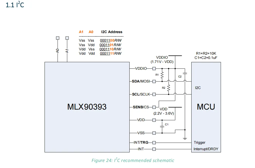
The typical application circuit for the MLX90393 I²C interface is structured such that VDD and VDDIO supply analog and digital power respectively;SDA / SCL are connected to the MCU via 10kΩ pull-up resistors for communication;SENB / CS are pulled high to select I²C mode; the logic levels of the A0 / A1 pins determine the I²C address; the INT / TRG and INT pins serve as interrupt/trigger signals, and a 0.1μF capacitor at the power supply terminal is used for filtering and decoupling.
2.6 Chip Configuration
None.
2.7 Communication Interfaces and Related Protocols
2.7.1 I2C Communication
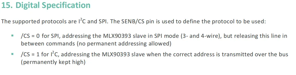
MLX90393 supports I²C and SPI two types of Communication Protocols, and the mode is selected via the pin level of SENB / CS: when pulled low, it is in SPI mode (supports 3-wire / 4-wire configuration, kept low during communication and released when idle); when pulled high, it is in I²C mode (needs to be kept at a high level permanently, and addressing is performed via the I²C address).
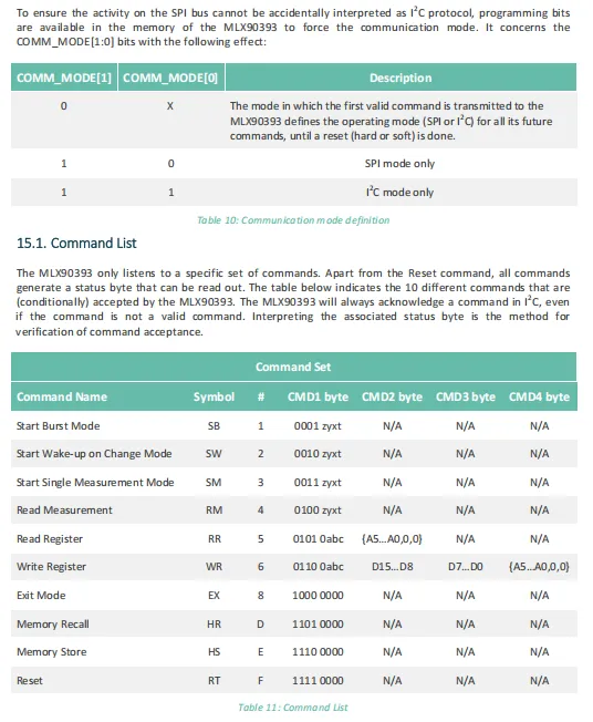
MLX90393 can configure the communication mode via COMM_MODE[1:0], supporting SPI - only, I²C - only or first-command locking mode. It also defines 10 basic commands, including Burst / single measurement, register read/write, reset, etc. The command format consists of CMD1 - CMD4 bytes, and all commands (except reset) return a status byte for verification.
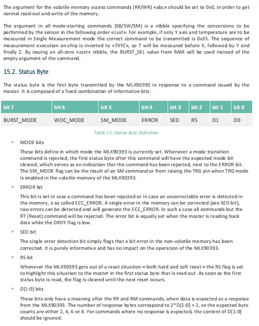
MLX90393 Regarding the command parameters and status byte: the lower 4 bits of the mode start command (zyxt) are used to specify the measurement channel, with the measurement sequence being T→X→Y→Z; the status byte is the chip's initial response to the host command, containing information about the current operating mode, error flags, memory error correction, reset status and data length, which can be used for command verification and error diagnosis.
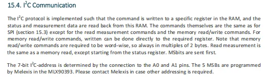
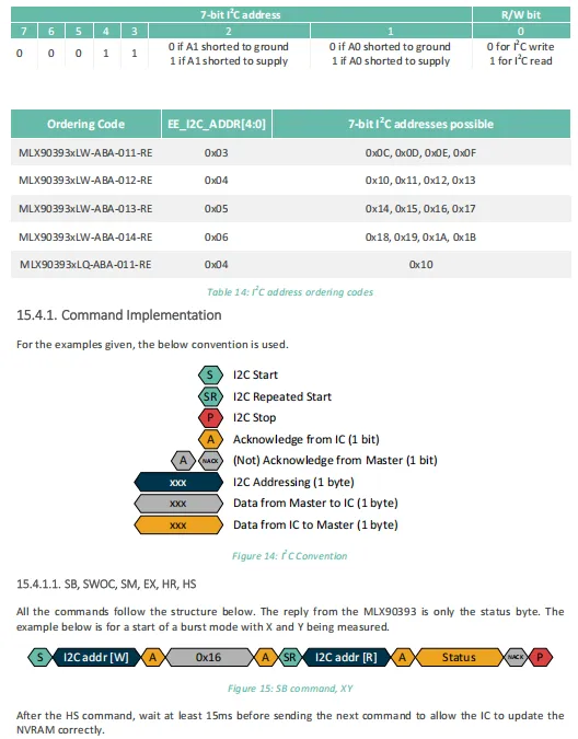
MLX90393 's I²C communication is implemented based on RAM registers. Its commands are basically compatible with those of SPI, but there are differences in read-write measurement and memory operations. Memory read and write must be performed in words (2 bytes), and the most significant bit (MSB) is transmitted first during data transfer; the 7-bit address is determined by the pin levels of A0 / A1 and the upper 5 bits preset by the chip, different order numbers correspond to different address ranges, and it also defines the I²C command timing conventions and the read-write flow of typical commands (such as SB).
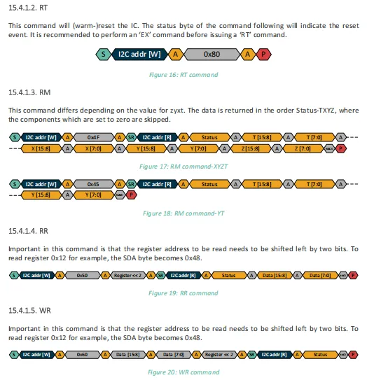
MLX90393 I²C command timings, including: RT (soft reset) command single-byte write timing, RM (read measurement) command returns data of different channels according to the zyxt parameter (e. g. in XYZT / YT formats), RR (read register) and WR (write register) commands require the register address to be shifted left by two bits before transmission, and all commands consist of address, data transmission and status return procedures.
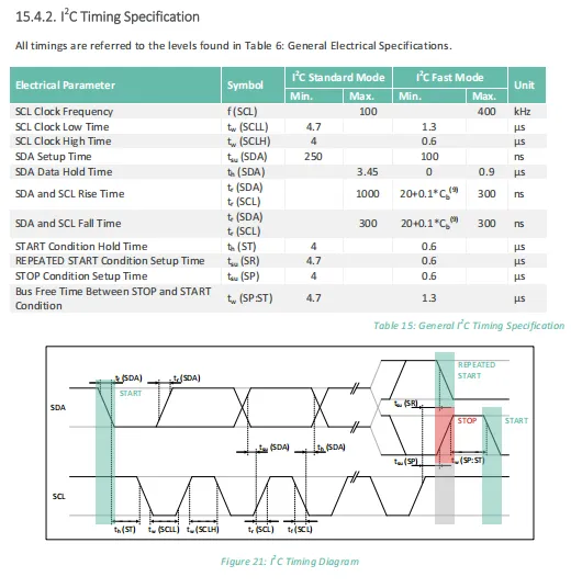
MLX90393 's I ² C standard mode (≤ 100kHz) and fast mode (≤ 400kHz) have key parameters such as clock frequency, high and low level time, data establishment/holding time, and start/repeat start/stop conditions. The signal stages corresponding to each parameter are intuitively displayed through Sequence Diagram, which is the timing constraint basis for designing I ² C communication.
2.7.2 Registers
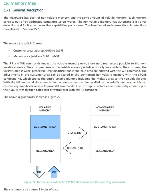
MLX90393 features 1Kbit non-volatile memory and 1Kbit volatile memory, both divided into 64 16-bit word addresses. The customer area (0x00 – 0x1F) is readable and writable, while the Melexis area (0x20 – 0x3F) is write-protected. Synchronization between volatile and non-volatile data is achieved via the HS (store) and HR (recall) commands, and the HR operation is executed automatically upon power-up or reset.
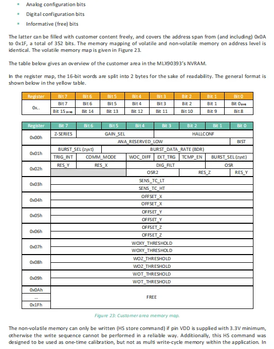
MLX90393 Memory map of the customer area (0x00 to 0x1F), covering analog configurations (e. g., gain, Hall settings), digital configurations (e. g., communication mode, filtering, offset calibration) and free bits (0x0A to 0x1F). Writing to non-volatile memory requires VDD ≥ 3.3V, and it is recommended to use it only once during calibration.
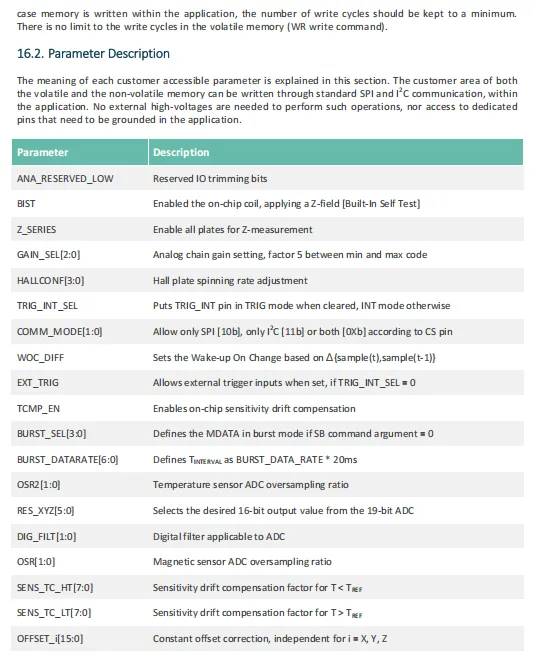
MLX90393 The customer zone memory features key register bits configurable via SPI / I²C, covering functions including analog (gain, Hall configuration, built-in self-test), digital (communication mode, wake-up trigger, filtering/oversampling), as well as temperature compensation and offset calibration. All configurations can be written via standard communication without requiring additional high voltage or dedicated pins.
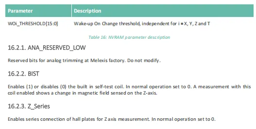
The memory of MLX90393 defines WOi_THRESHOLD as the independent change wake-up thresholds for the X, Y, Z axes and the temperature channel, specifies that ANA_RESERVED_LOW is the reserved bit for factory analog calibration, BIST is the built-in self-test coil switch (set to 0 for normal operation), and Z_Series is the series mode switch for the Z -axis Hall plate (set to 0 for normal operation); all of these bits must be configured in accordance with the specifications to ensure proper functionality.
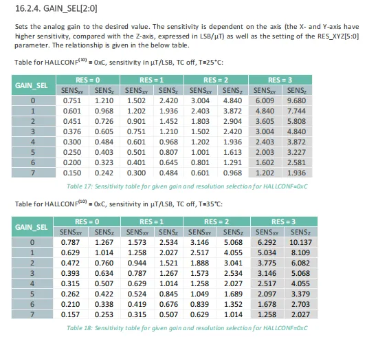
MLX90393 with the gain (GAIN_SEL[2:0]) and resolution (RES_XYZ[5:0]) configured, provides a comparison table of the sensitivity (unit: μT/LSB) of the X / Y axes and Z axis at different temperatures (25℃/35℃). It shows that the lower the gain and resolution, the higher the sensitivity, and the sensitivity of the X / Y axes is generally higher than that of the Z axis, which serves as a key parameter basis for magnetic field measurement accuracy calibration.
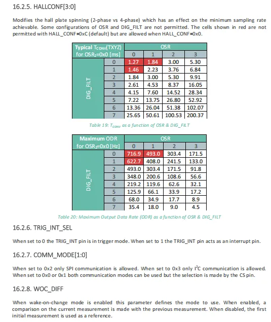
MLX90393 's HALLCONF determines the sampling phase of the Hall plate, and together with the oversampling ratio (OSR) and digital filter (DIG_FILT), affects the conversion time (Tconv) and maximum output data rate (ODR); some combinations are not allowed under the default configuration;TRIG_INT_SEL is used to configure the TRIG_INT pin to trigger or interrupt mode;COMM_MODE can be fixed as SPI / I²C or dynamically selected via the CS pin for communication mode;WOC_DIFF defines the reference comparison method in wake-on-change mode.
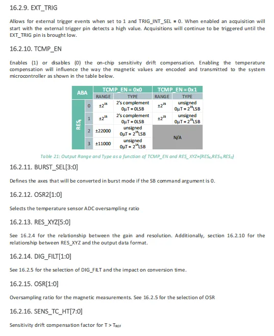
The EXT_TRIG of MLX90393, in conjunction with TRIG_INT_SEL, enables external trigger sampling;When TCMP_EN is enabled, it will change the encoding format and range of magnetic field data, which needs to be configured in combination with the RES_XYZ resolution;
BURST_SEL defines the channel that is measured by default in burst mode;
OSR2 / OSR set the temperature and magnetic field respectively, and ADC oversampling rate;
DIG_FILT digital filtering, RES_XYZ resolution, SENS_TC_HT and high-temperature sensitivity compensation, respectively affect the conversion time, output format and temperature stability.
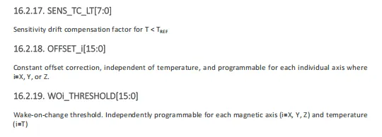
MLX90393 's SENS_TC_LT[7:0]is used to set the sensitivity drift compensation coefficient at low temperatures, OFFSET_i[15:0]provides independent, temperature-invariant constant offset correction for each axis, and WOi_THRESHOLD[15:0]can be separately configured as the change wake-up thresholds for the X, Y, Z axes and the temperature channel, which are applied in the low-power trigger mode.
2.8 PCB Routing Notes
None.
III. Circuit Engineering
3.1 Circuit Source Engineering
To obtain the source code of the circuit, please follow the official account [Freak Embedded]
3.2 Module Usage Instructions
The schematic diagram of this module is shown below:
SCH_Schematic1_3-Axis Hall Sensor Module Based on MLX90393_v1.0.0_2026-05-12.pdf 2.2 MB
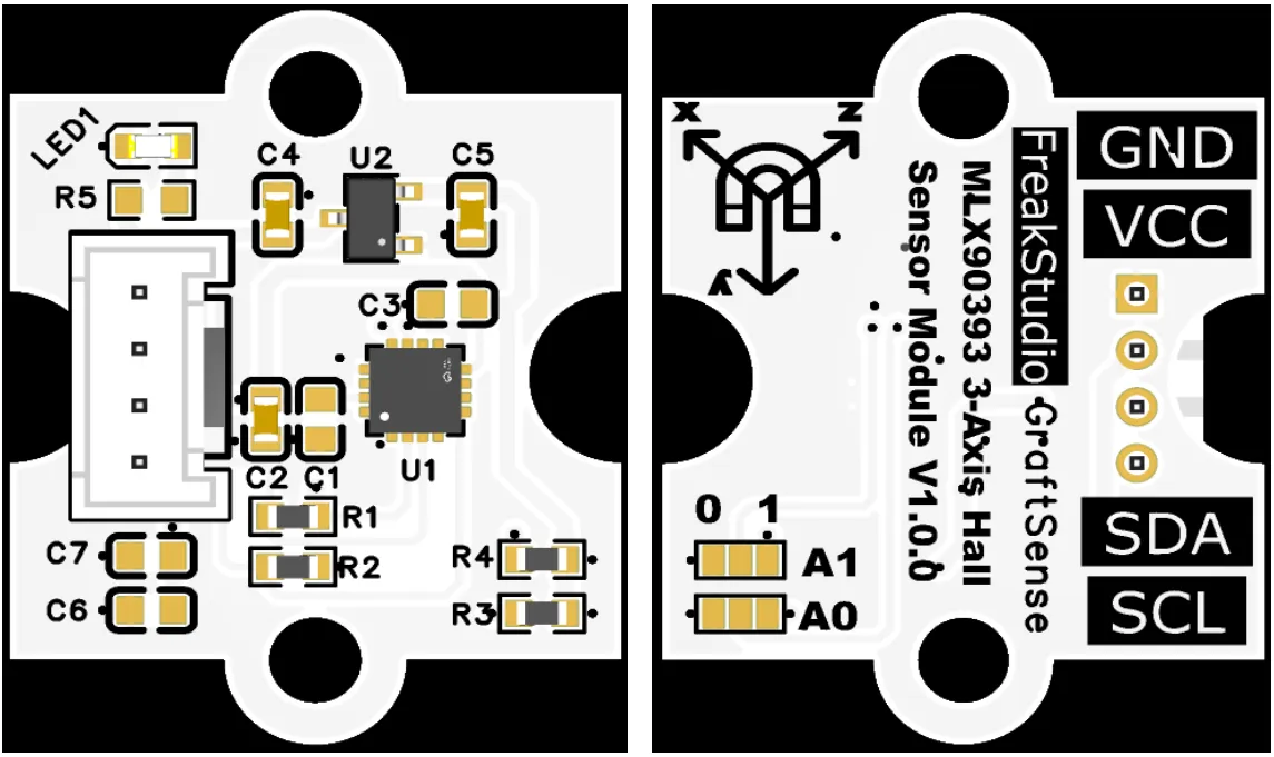
This module provides an IIC communication interface: it supports standard I2C communication rates, can flexibly configure multiple I2C pins, is compatible with 3.3V logic levels, and can stably transmit the 16-bit digital signals of three-axis (A0 and A1 pins, is compatible with 3.3V logic levels, and can stably transmit the 16-bit digital signals of three-axis (X / Y / Z) magnetic field intensity collected by the MLX90393. It is applicable to scenarios such as 3D joysticks, , position detection, electronic compasses, and IoT low-power magnetic field sensing devices, providing the system with reliable 3D position and angle sensing data interaction capabilities.
By configuring A0 and A1, two networks with short-circuited terminals, different I2C communication addresses can be set:

3.3 Application Experiment
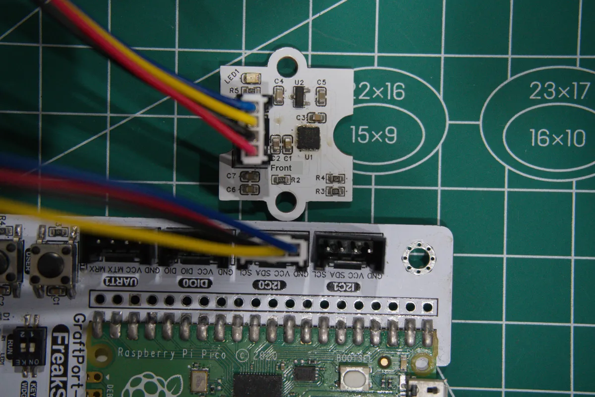
Here, we use the GraftPort-RP2040 development board for testing, and the MLX90393-based 3-axis Hall sensor module communicates with the main controller via the I2C interface.
Here, we first use the HY2.0-4P connection cable to connect the module to the GraftPort-RP2040 development board's I2C0 interface:
Development Board Pins | Module Pins | Description |
Pin 4 |
|
|
Pin 5 |
|
|
Here, we need to search for the relevant driver packages on uPyPI: https://upypi.net/zh/
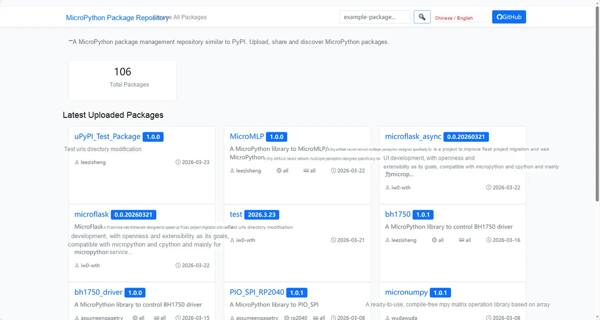
Enter mlx90393_driver to search, and the following will be displayed:

Click to copy the local installation command:
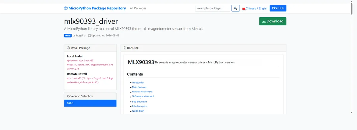
Import the module driver library code via the mip tool. Below are the usage commands for the mpremote tool:
mpremote mip install https://upypi.net/pkgs/mlx90393_driver/1.0.0Import the 3-axis Hall sensor module based on MLX90393 - MicroPython driver code, then copy the following main.py code into our project:
# Python env   : MicroPython v1.23.0
# -*- coding: utf-8 -*-
# @Time    : 2026/4/21 15:30
# @Author  : FreakStudio
# @File    : main.py
# @Description : Test code for MLX90393 three-axis magnetometer sensor driver
# @License : MIT

# ======================================== Import Modules =========================================

import time
from machine import Pin, SoftI2C
from micropython_mlx90393 import mlx90393

# ======================================== Global Variables ============================================

# I2C pin configuration
I2C_SDA_PIN = 4
I2C_SCL_PIN = 5

# Target sensor I2C address list
TARGET_SENSOR_ADDRS = [0x0C]

# Measurement loop delay (seconds)
MEAS_DELAY_S = 1

# ======================================== Functions ============================================

# ======================================== Custom Classes ============================================

# ======================================== Initialization ==========================================

time.sleep(3)
print("FreakStudio: MLX90393 magnetometer test starting ...")

# Initialize I2C bus
i2c_bus = SoftI2C(sda=Pin(I2C_SDA_PIN), scl=Pin(I2C_SCL_PIN))

# Scan the I2C bus
devices_list = i2c_bus.scan()
print("I2C scan result: %s" % [hex(d) for d in devices_list])

if len(devices_list) == 0:
    raise RuntimeError("I2C scan found no devices")

# Find the target sensor address
sensor = None
for device_addr in devices_list:
    if device_addr in TARGET_SENSOR_ADDRS:
        print("Target sensor found at address: %s" % hex(device_addr))
        sensor = mlx90393.MLX90393(i2c=i2c_bus)
        break

if sensor is None:
    raise RuntimeError("Target sensor not found on I2C bus")

print("Sensor initialization successful")

# ========================================  Main Program  ===========================================
while True:
        # Read the X/Y/Z three-axis magnetic field values (microtesla)
        magx, magy, magz = sensor.magnetic
        print("X: %.2f uT | Y: %.2f uT | Z: %.2f uT" % (magx, magy, magz))
        time.sleep(MEAS_DELAY_S)
Burn the code, open the terminal, and the output is as follows:
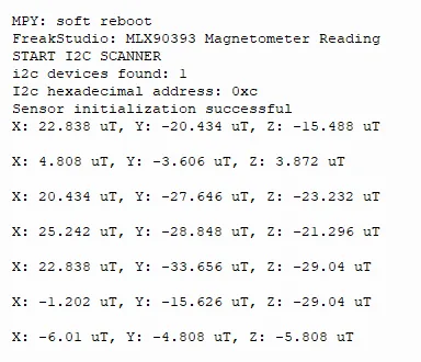
The MLX90393 magnetometer features normal I2C communication and initialization, can stably output three-axis magnetic field data, with values updated in real time as the sensor's attitude changes, and operates with normal response.
IV. Drivers
mlx90393_driver-1.0.0.zip 13 KB
5. BOM & Recommended Alternative Parts
None.
6. Revision History
Document Version | Date of Revision | Modifier | Modified Content |
v1.0 | 2026-05-12 | Ling Gaoxing | Initialize the document |
v1.1 | 2026-06-03 | Xin Ruili | Create an open version of the document based on the internal document version v1.0. |
VII. Relevant Materials
7.1 Chip Datasheet
MLX90393.pdf 707 KB
7.2 Unique Icons for PCB Silk Screen