Contents
- I. Module Introduction
- II. Introduction to Main Chips
- 2.1 Chip Overview
- 2.2 Pin Definition
- 2.3 Functional Block Diagram
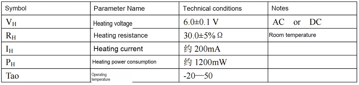
- 2.4 Performance Parameters
- 2.5 Reference Circuit
- 2.6 Chip Configuration
- 2.7 Communication Interfaces and Related Protocols
- 2.8 PCB Routing Precautions
- III. Circuit Engineering
- 3.1 Circuit Source Engineering
- 3.2 Module Usage Instructions
- 3.3 Application Experiment
- IV. Drivers
- 5. BOM & Recommended Alternative Parts
- VI. Revision History
- VII. Relevant Materials
I. Module Introduction
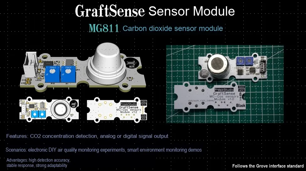
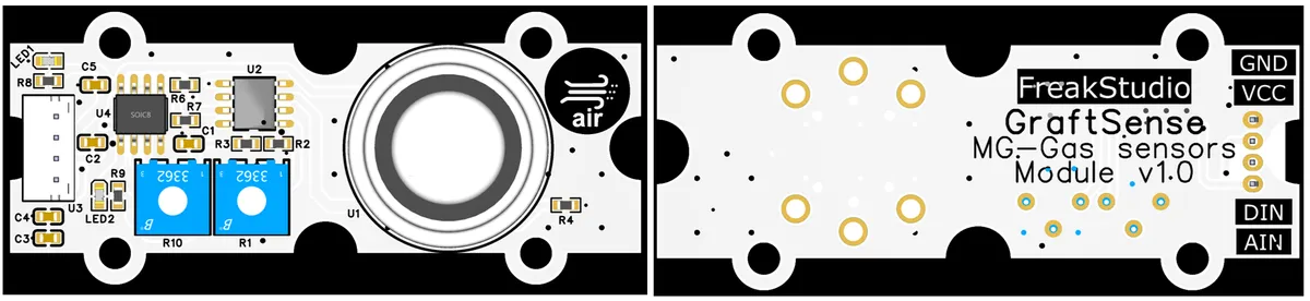
MG811 Carbon Dioxide Sensor Module takes the solid electrolyte (NASICON) based MG811 sensor as the core, and realizes concentration sensing by detecting the electromotive force generated by its electrode reaction (which is inversely proportional to the logarithm of CO₂ concentration). In the circuit diagram, the heating electrode of the sensor needs to be matched with a power supply of about 6V; the weak electromotive force output by the signal electrode is amplified in the same direction by the CA3140 high-impedance operational amplifier (with an amplification factor of about 8.5 times) and then outputs an analog signal from the AOUT terminal. Meanwhile, the amplified signal is compared with the reference voltage through the LM393 voltage comparator, and outputs a digital signal from DOUT to realize over-limit trigger. Supported by auxiliary circuits such as filtering and decoupling, power supply and alarm indication, the module has a detection range of 0–10000ppm, integrates both analog quantitative detection and digital qualitative alarm functions, and is widely used in scenarios such as smart home ventilation control, greenhouse monitoring, and industrial fermentation monitoring.
II. Introduction to Main Chips
This module mainly uses MG811 probe, CA3140AMZ96-MS high-impedance operational amplifier and LM393BIDR voltage comparator.
2.1 Chip Overview
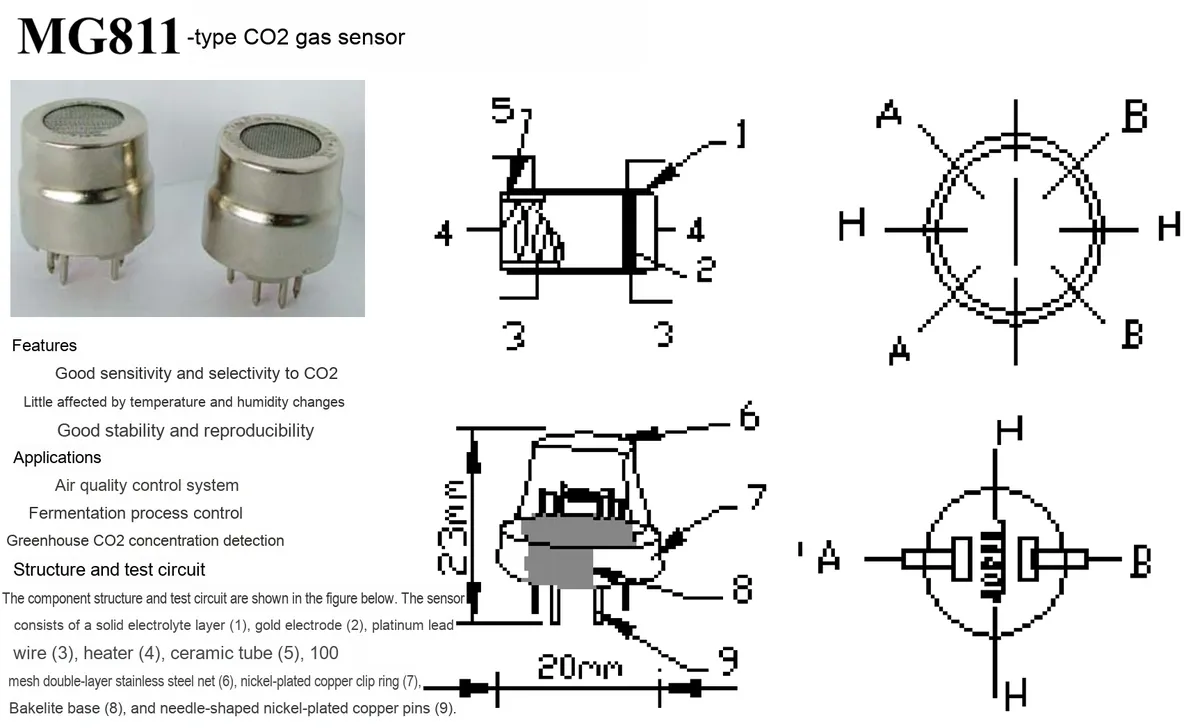
The MG811 carbon dioxide sensor operates based on the principle of solid electrolyte cells, and its electrochemical structure is as follows:
Air → Au electrode | NASICON (solid electrolyte) || Carbonate | Au electrode → CO₂-containing air.
When in a CO₂ atmosphere, the following electrode reaction occurs:
- Negative electrode:
2Li++CO2+21O2+2e−=Li2CO3 - Positive electrode:
2Na++21O2+2e−=Na2O - Overall reaction:
Li2CO3+2Na+=Na2O+2Li++CO2
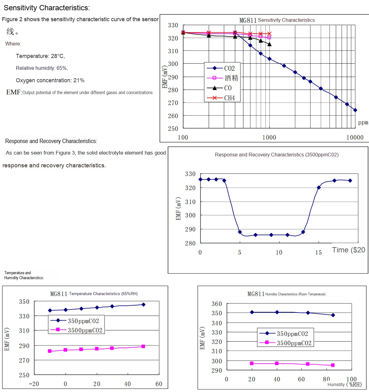
The potential difference (EMF) between the sensor's sensitive electrode and reference electrode conforms to the Nernst equation: EMF = Ec −2 FR × T ln (P (CO2))
, where P (CO2) is the partial pressure of CO₂, Ec is a constant, R is the gas constant, T is the absolute temperature (K), and F is the Faraday constant. It can be seen that the output potential is inversely proportional to the logarithm of the CO₂ partial pressure, which can reflect the change in CO₂ concentration.
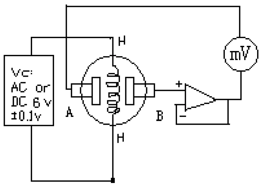
In addition, an external circuit is required to supply a heating voltage to the sensor, so that its surface temperature is high enough to form an effective "battery" and output a voltage signal; besides, during measurement, the impedance of the amplifier 100~1000 GΩ shall be within this range, and the test current shall be controlled below 1 pA, so as to ensure the detection accuracy of the weak potential signal and avoid interfering with the electrochemical characteristics of the battery.
2.2 Pin Definition
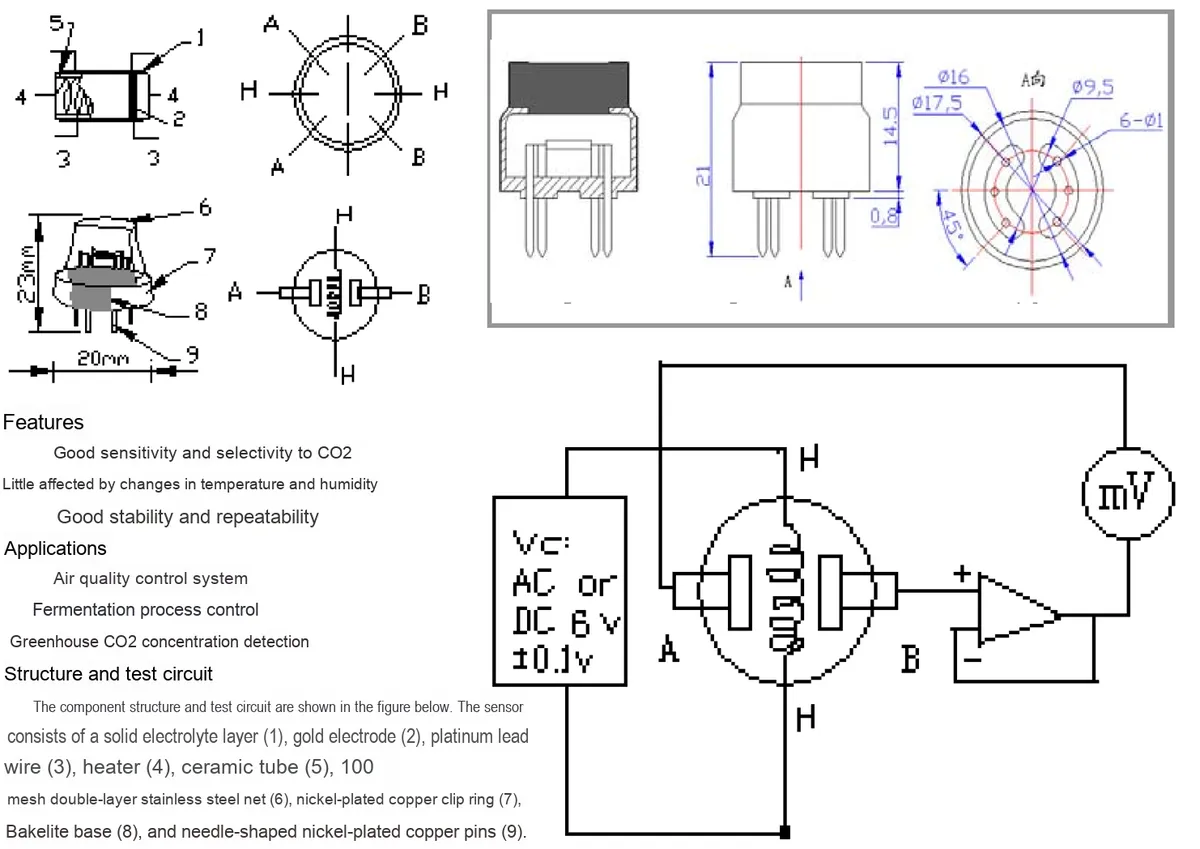
The pins of the MG811 carbon dioxide sensor probe mainly serve two functions: heating power supply and signal output, with the specific definitions as follows:
- Signal output pins:
AandBare the leads of the gold electrodes (sensing/reference electrode), which are used to output the weak potential difference (EMF) related toCO₂concentration, and require an external amplifier with high input impedance (100–1000 GΩ) for detection; - Heating supply pin:
His the power supply pin of the heater, which needs to be connected to aAC or DC 6V±0.1V power supplyto provide the temperature conditions required for the sensor to operate and ensure the normal progress of the electrochemical reaction of the solid electrolyte.
2.3 Functional Block Diagram
None.
2.4 Performance Parameters

2.5 Reference Circuit
2.6 Chip Configuration
None.
2.7 Communication Interfaces and Related Protocols
None.
2.8 PCB Routing Precautions
There are no special requirements, except that this electronic module requires a relatively large current (about 200mA), so pay attention to widening the traces during wiring.
III. Circuit Engineering
3.1 Circuit Source Engineering
To obtain the circuit source project, please follow the official account [Freak Embedded]
3.2 Module Usage Instructions
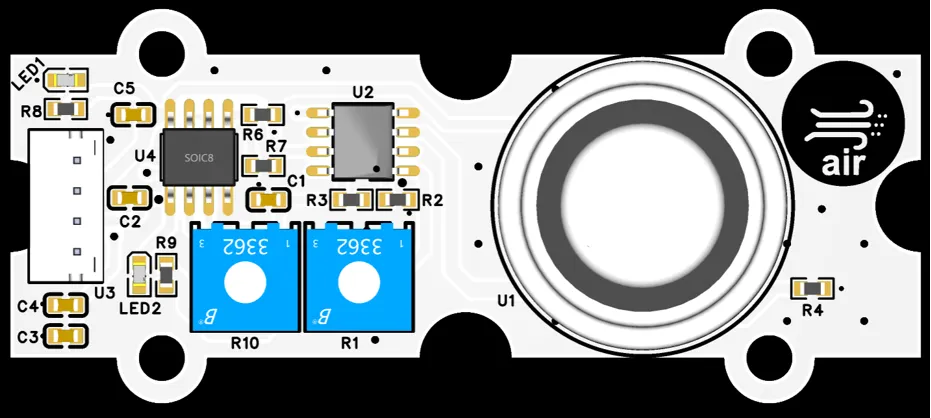
The schematic diagram of this module is shown below:
SCH_Schematic1_MG811 Carbon Dioxide Sensor Module_v1.1_2025-09-16.pdf 3.1 MB
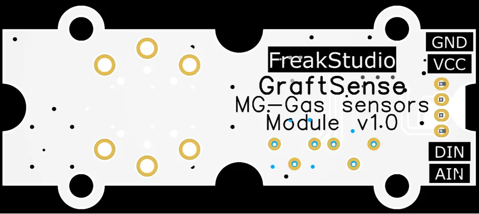
This module provides two types of output interfaces:
- Analog Output (
AIN): This is the output of the amplified original analog signal. Users can directly acquire it through the ADC (Analog-to-Digital Converter) pin of the main control chip to read the amplified analog voltage value. - Digital Output (
DIN): This is the digital signal output processed by the voltage comparator. It is a high-level or low-level signal that can be directly connected to the GPIO pin of the main control chip. When the voltage ofAINis higher than the set threshold voltage,DINoutputs one level; when the voltage is lower than the threshold, it outputs another level, which can be used for signal threshold judgment or state detection.
As shown in the schematic diagram, the core part of its circuit consists of an operational amplifier circuit and a voltage comparison circuit:
- Non-inverting amplifier circuit (based on
U2:CA3140operational amplifier):The weak electromotive force of MG811is subjected to non-inverting amplification by theCA3140high-impedance operational amplifier. In the circuit,R1(100kΩ),R2(10kΩ), andR3(20kΩ) form a feedback network with an amplification factor of approximately 8.5. The amplified analog signal is output fromAOUTand can be directly connected to anADCfor concentration conversion;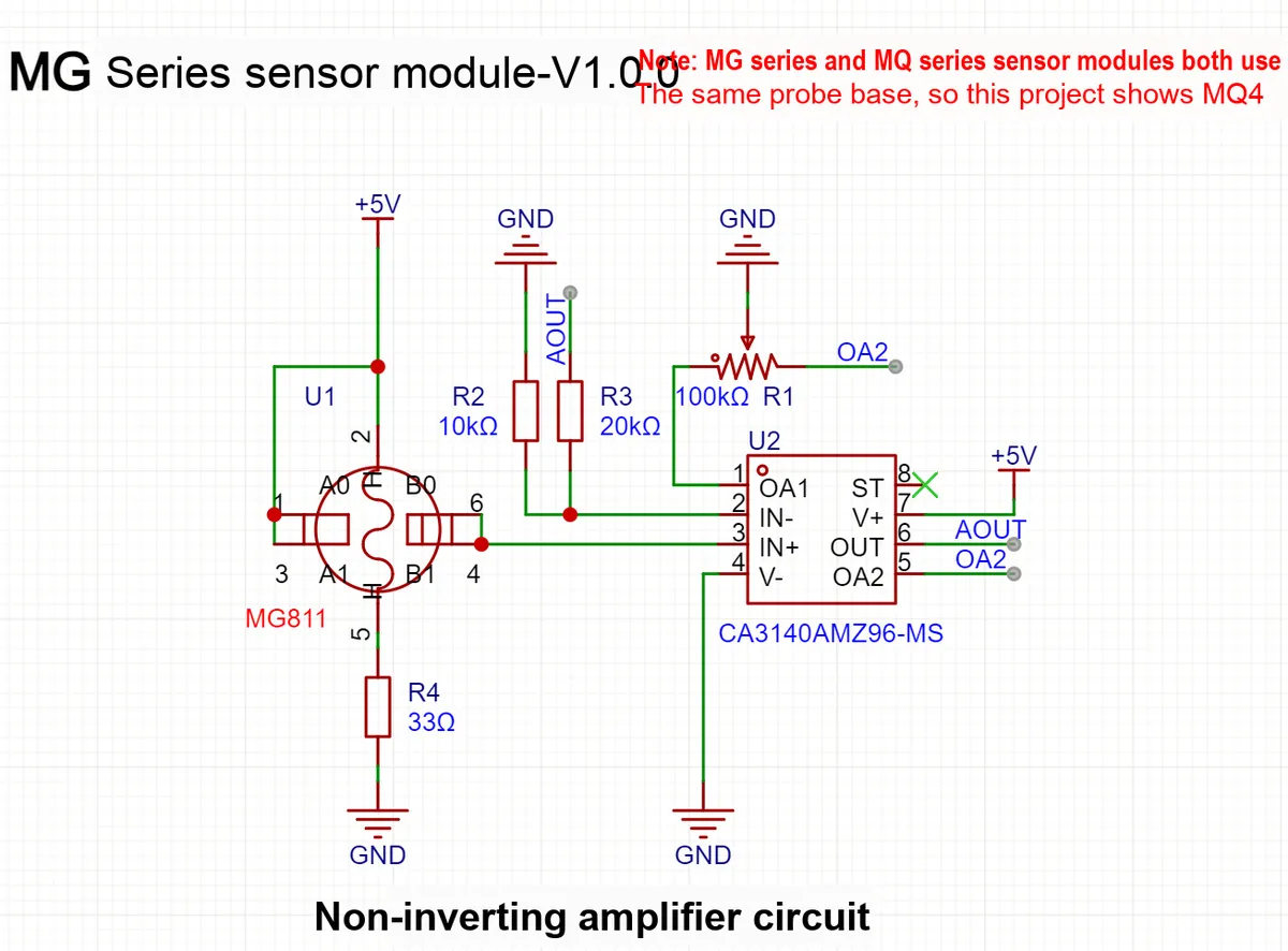
- Voltage comparison circuit (based on
U4.1:LM393operational amplifier): The amplified analog signal (AOUT) is compared with a reference voltage (generated by voltage division viaLM393voltage comparator) throughR6andR7, and outputs a digital signalDOUT. This circuit can set a threshold (e. g., corresponding to a specificCO₂concentration) to achieve over-limit alarm or trigger control logic (such as the start/stop of a ventilation system).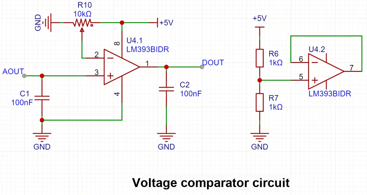
Adjusting R10 (10kΩ) will change the threshold level of the voltage comparison circuit, thereby affecting the "alarm trigger point" of the module for CO₂ concentration. The larger the resistance value, the higher the CO₂ concentration required to trigger the alarm; the smaller the resistance value, the lower the CO₂ concentration that triggers the alarm.
3.3 Application Experiment
Here, we use the GraftPort-RP2040 development board for testing, and connect the MG811 carbon dioxide sensor module to communicate with the main controller via the AIN interface.
Here, we first use the HY2.0-4P cable to connect the module to the GraftPort-RP2040 development board's AIN0 interface:
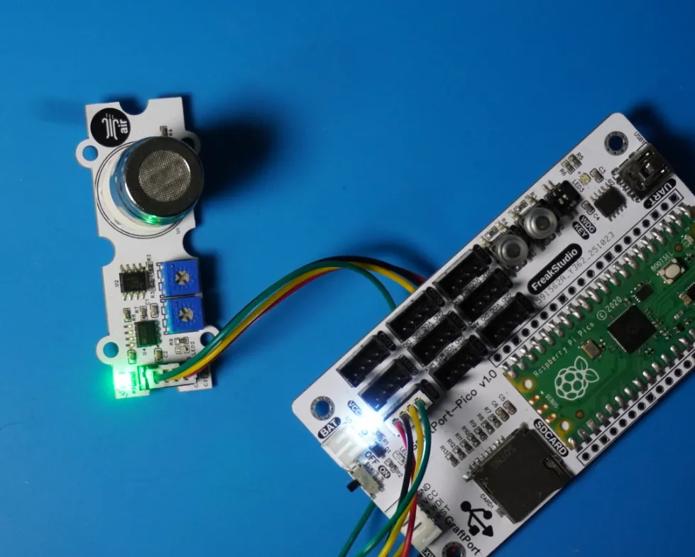
The module connections are shown in the following table:
development board pins | Module Pins | Description |
Pin 26 |
| Sensor analog signal input pin |
Pin 19 |
| Digital signal input pin after digital comparison of sensor analog signals |
Before burning the code, we first need to adjust the digital output threshold of the MG811 carbon dioxide sensor module:
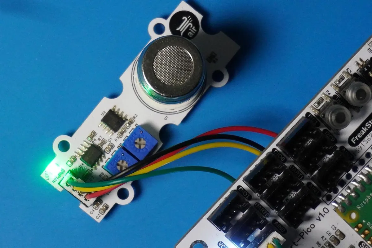
- Ensure the sensor is in normal air and has been fully warmed up, then locate the "threshold adjustment variable resistor
R5"(marked with a red circle in the figure) on the module; - Turn this counterclockwise while observing
LED2(sensor trigger indicator); - Stop the operation when
LED2is just fully lit, then slightly adjust it back to the position where it goes out; at this point, the sensor has been calibrated to a reasonable threshold in an air environment.
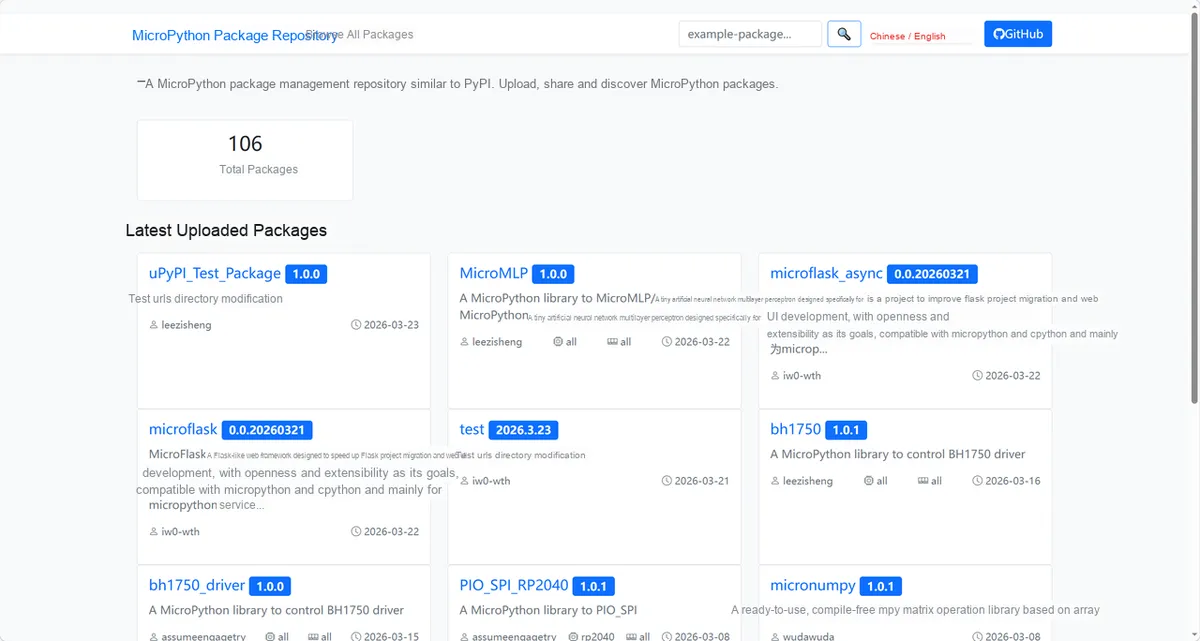
Here, we need to search for the relevant driver packages on uPyPI: https://upypi.net/zh/
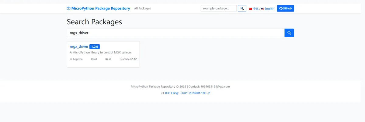
Enter mgx_driver to search, and the following will be displayed:
Click to copy the local installation command:
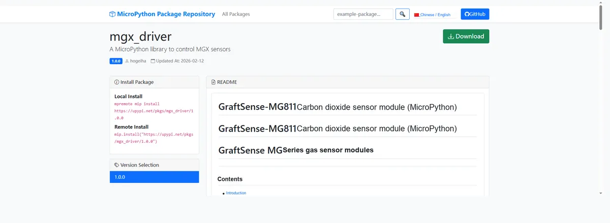
Here, we can import the module driver library code via the mip tool. Below are the usage commands for the mpremote tool:
mpremote mip install github:FreakStudioCN/GraftSense-Drivers-MicroPython/sensors/mgx_driverAfter importing the MG carbon dioxide sensor module - MicroPython driver code, copy the following main.py code into our project:
# Python env   : MicroPython v1.23.0
# -*- coding: utf-8 -*-
# @Time    : 2025/08/20 10:21
# @Author  : 缪贵成
# @File    : main.py
# @Description : Test the MG series gas sensor module driver program

# ======================================== Import Modules =========================================

from machine import Pin, ADC
import time
from time import sleep
from mgx import MGX

# ======================================== Global Variables ============================================

# ======================================== Functions ============================================

# User callback function
def mg_callback(voltage: float) -> None:
    """
    Called when the comparator pin triggers an interrupt; prints the current voltage value.

    Args:
        voltage (float): Voltage value (unit: V).

    ==========================================

    This function is called when the comparator pin triggers an IRQ,
    and prints the measured voltage.

    Args:
        voltage (float): Voltage value in volts.

    """
    print("[IRQ] Voltage: {:.3f} V".format(voltage))

# ======================================== Custom Classes ============================================

# ======================================== Initialization ==========================================

# Power-on delay of 3 s
time.sleep(3)
# Print debug message
print("Measuring Gas Concentration with MG Series Gas Sensor Modules")

# Pico ADC0 (GPIO26)
adc = ADC(Pin(26))
# Comparator output (GPIO15, optional)
comp = Pin(19, Pin.IN)
mg = MGX(adc, comp, mg_callback, rl_ohm=10000, vref=3.3)

# Select a built-in polynomial (MG811, MG812)
mg.select_builtin("MG811")

# Pass in a custom polynomial
# mq.set_custom_polynomial([1.0, -2.5, 3.3])

# ========================================  Main Program  ===========================================

print("===== MG Sensor Test Program Started =====")
try:
    while True:
        # Read voltage
        v = mg.read_voltage()
        print("Voltage: {:.3f} V".format(v))

        # Read ppm (5 samples, 200 ms interval)
        ppm = mg.read_ppm(samples=5, delay_ms=200)
        print("Gas concentration: {:.2f} ppm".format(ppm))

        print("-" * 40)
        # Main loop interval
        sleep(2)
except KeyboardInterrupt:
    print("User interrupted, exiting program...")
finally:
    mg.deinit()
    print("Sensor resources released.")
To flash the code, open a terminal and use the mpremote tool to connect to the main controller; the output is as follows:
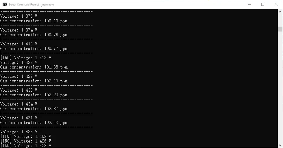
When no trigger occurs, it will print the pin voltage and gas concentration; when the sensor's trigger state changes, the callback function mg_callback will be invoked. In the example, when the callback function is triggered, the content [IRQ] will be printed, and at the same time LED2 (the sensor trigger indicator) will light up.
It should be noted here that our MG811 carbon dioxide sensor module only supports qualitative gas identification and cannot directly achieve quantitative detection (the coefficients in the code are simulated values rather than real ones).
To achieve quantitative measurement capability, a professional calibration process is required: simulate different temperature and humidity environments by means of a high-low temperature alternating chamber, use standard calibration gas samples corresponding to the target gas, collect the analog voltage signals output by the sensor under various environmental conditions, and finally establish a correlation model of "temperature and humidity - gas concentration - output voltage" through curve fitting to complete the calibration for quantitative detection.
Here, we briefly explain the calibration concept for you. First, professional calibration equipment and consumables need to be prepared, and the core configurations include a high-low temperature alternating test chamber (used to simulate different temperature and humidity environments and eliminate the interference of environmental factors on sensor output), target gas standard samples with multiple gradient concentrations (which need to match the detection range of the sensor, such as combustible gas standard gas with a gradient of 0-1000ppm), and a gas test chamber (whose core function is to provide a sealed and uniform standard gas environment for the sensor probe to ensure the accuracy of calibration data).
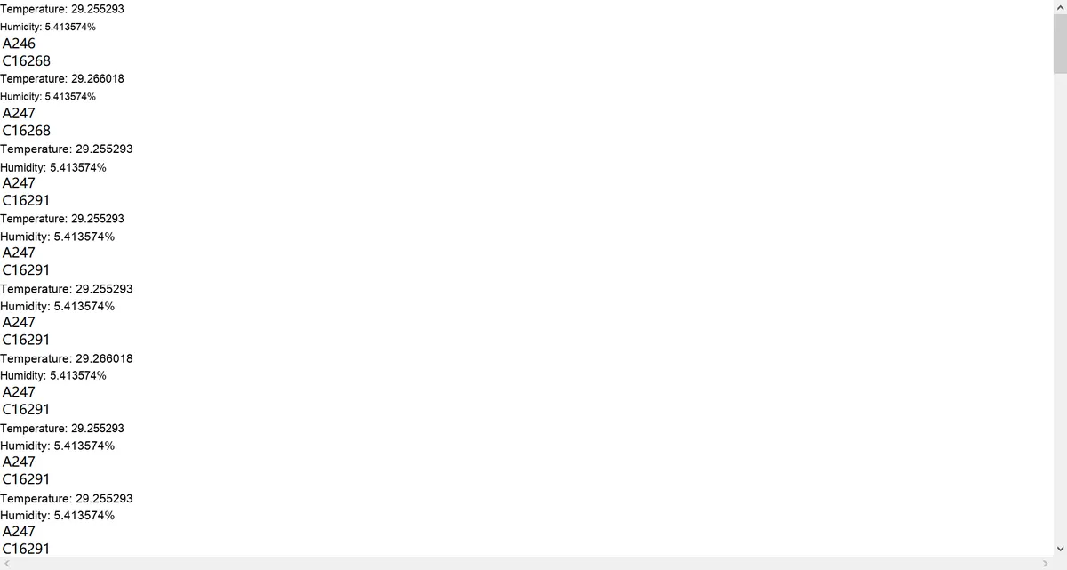
Next, on the embedded device side, collect the temperature value, humidity value, voltage output and the gas concentration value of the calibration gas near the probe, and save them to a file (it is required to collect as much data as possible under different temperature, humidity and gas concentration conditions after the probe is powered on in advance and fully preheated):
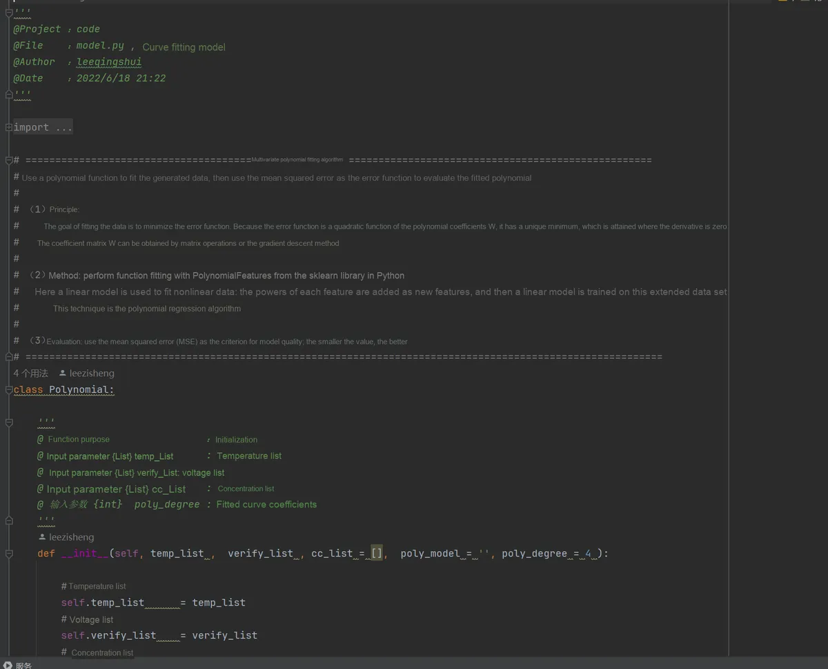
Then, on the PC side, you can use Python to write code for data fitting, which includes:
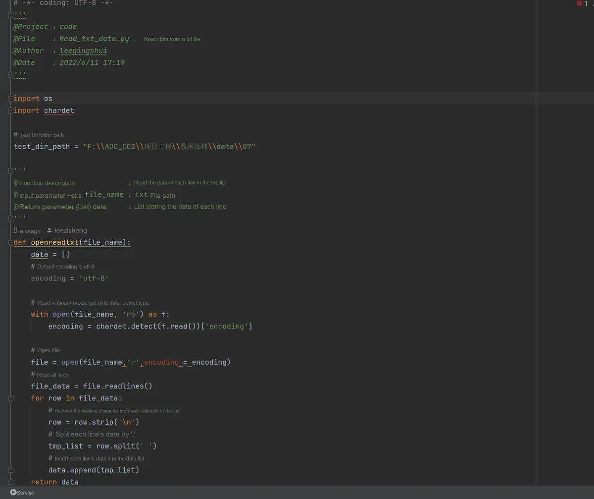
- Batch read multiple
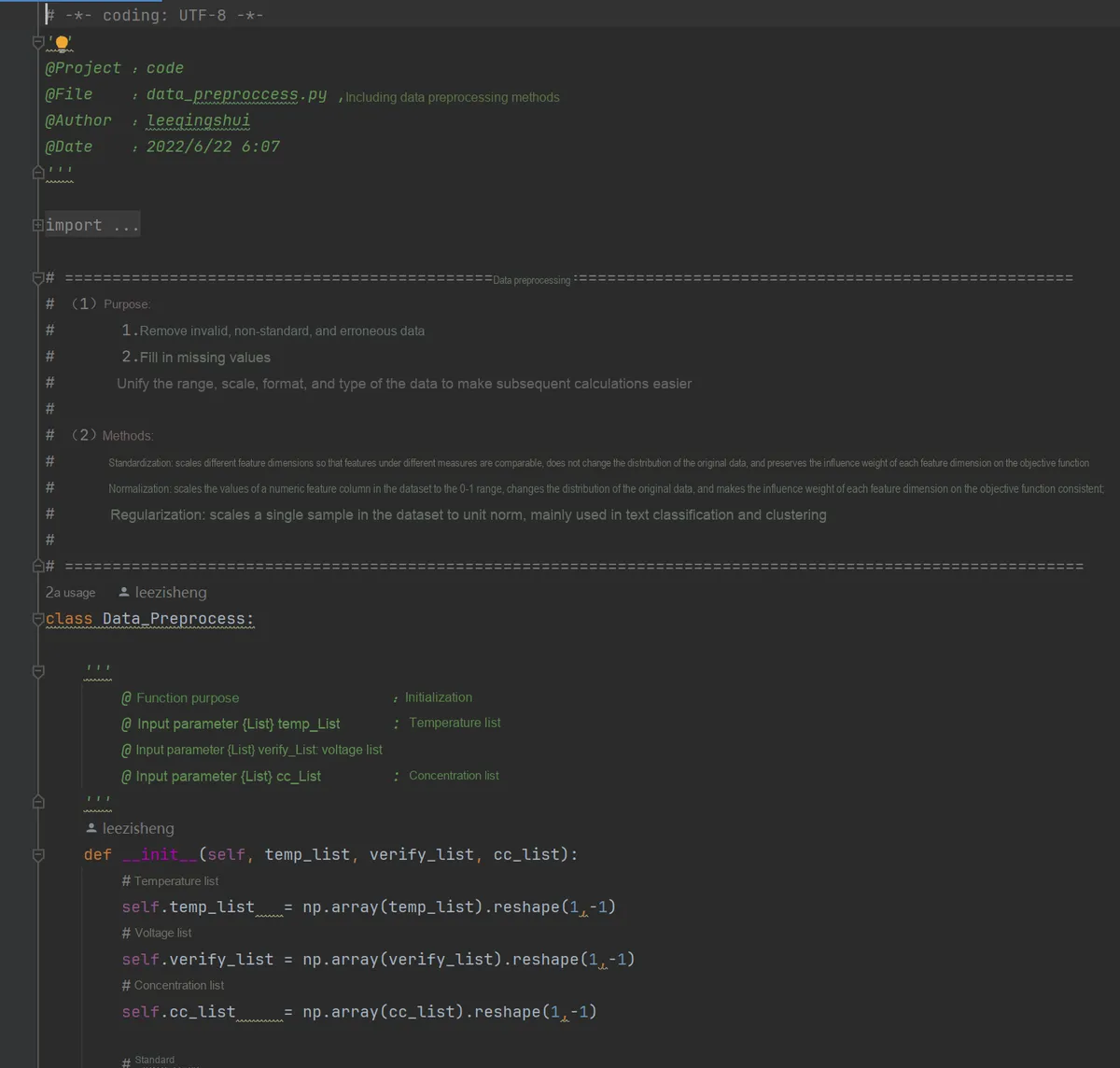
TXTformatted raw sensor data files, automatically adapt to file encoding formats, filter blank lines, and convert text data into numerical format; - Perform cleaning preprocessing on the raw data, eliminate outliers with temperature and voltage beyond the measurement range, and fill in missing values with column mean to ensure the validity of the fitted data;
- Normalize the temperature and voltage features, scale the values to the range of 0 to 1, and eliminate the interference of dimensional differences between different features on the fitting results;
- call
sklearn'sPolynomialFeaturesto generate polynomial features (such as temperature², temperature × voltage, voltage², etc.), so as to realize the transformation of nonlinear data for linear fitting; - Split 80% of the data into the training set and 20% into the test set, and train the polynomial fitting parameters based on linear regression via Model Training;
- We take the mean squared error (
MSE) as the core evaluation metric to quantify the accuracy of the fitting model (the smaller the MSEvalue, the better the fitting effect); - Export the trained polynomial coefficients and intercept to provide core parameters for concentration calculation on the embedded device side;
- Visualize the fitted curve to intuitively compare the deviation between the actual concentration value of the sensor and the predicted value of the model, so as to assist in optimizing the polynomial order.
IV. Drivers
mgx_driver.zip 11 KB
5. BOM & Recommended Alternative Parts
None.
VI. Revision History
Document Version | Revision Date | Modifier | Revised Content |
v1.0 | 2025.8.31 | Xing Gao | Initialize Document |
v1.1 | 2025-09-17 | Li Zisheng | Added 2.8 PCB routing precautions Revised Section 3, Instructions for Circuit Source Project and Module Usage, and added a secondary heading: 3.1 Circuit Source Engineering, 3.2 Module Usage Instructions, 3.3 Application Experiments The BOM sheet has not been finally checked, the driver has not been re-verified, and the 3.3 application experiment Not yet specified. |
v1.2 | 2025-12-29 | Li Zisheng | Added application experiments and production files |
v1.3 | 2025-12-31 | Sin Ruili | Create an open version of the document based on the internal document version v1.2. |
v1.4 | 2026-03-29 | Sin Ruili | Modified the application experiment section. |
VII. Relevant Materials
7.1 Chip Datasheet
MG811 CO2 Gas Sensor.pdf 128 KB
CA3140AMZ96-MS Datasheet.pdf 974 KB
LM393BIDR Datasheet.pdf 3.4 MB
7.2 Unique Icons for PCB Silk Screen