Contents
- I. Module Introduction
- II. Introduction to Main Chips
- 2.1 Chip Overview
- 2.2 Pin Definition
- 2.3 Functional Block Diagram
- 2.4 Performance Parameters
- 2.5 Reference Circuit
- 2.6 Chip Configuration
- 2.7 Communication Interfaces and Related Protocols
- 2.8 PCB Routing Precautions
- III. Circuit Engineering
- 3.1 Circuit Source Engineering
- 3.2 Module Usage Instructions
- 3.3 Application Experiment
- IV. Drivers
- 5. BOM & Recommended Alternative Parts
- VI. Revision History
- VII. Relevant Materials
- 7.1 Chip Datasheet
- 7.2 Unique Icons for PCB Silk Screen
I. Module Introduction
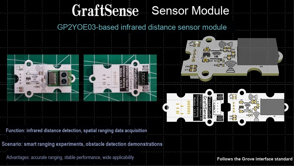
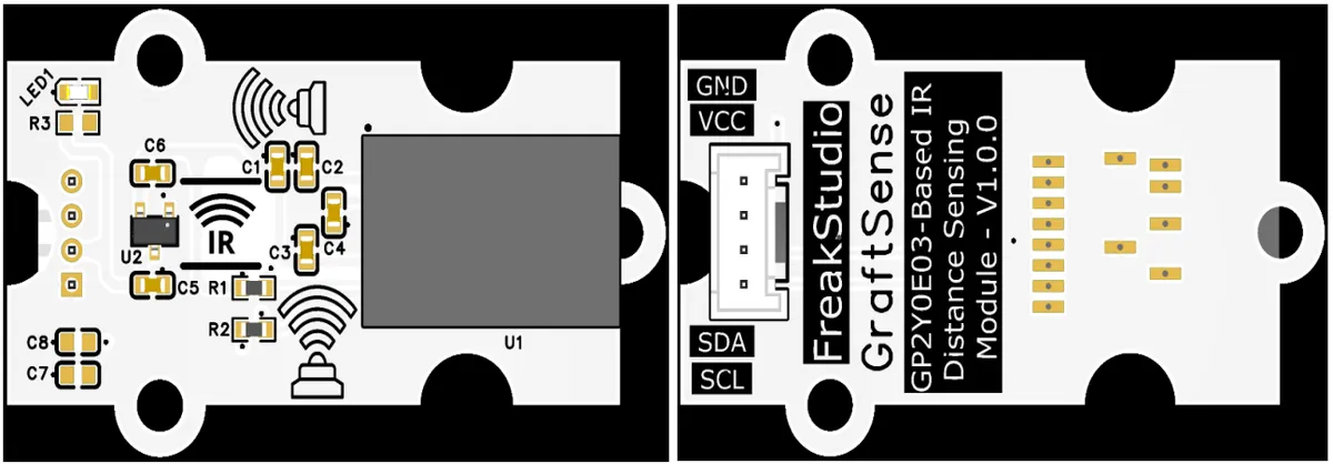
GP2Y0E03-based infrared ranging sensor module adopts Sharp GP2Y0E03 infrared ranging chip solution, realizes non-contact distance detection within 4~50cm through the infrared triangulation ranging principle, and can directly output digital distance values; the module is equipped with LDO voltage regulator circuit, power filter and indicator circuit, powered by 3.3V and supports I2C digital communication, with millimeter-level resolution, which is suitable for distance detection scenarios such as robot obstacle avoidance, position detection, and automatic sensing devices.
II. Introduction to Main Chips
GP2Y0E03 is an infrared ranging sensor from Sharp that adopts the triangulation method, supports a ranging range of 4–50 cm, and features I²C digital and analog dual outputs, a compact form factor, low voltage operation (2.7–5.5V) and high precision.
2.1 Chip Overview
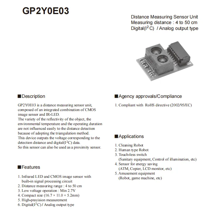
GP2Y0E03 is an infrared ranging sensor that adopts the triangulation method, with a built-in infrared LED and CMOS image sensor. It features a ranging range of 4–50cm, supports dual output of I²C digital signal and analog voltage, operates at a voltage as low as 2.7V, and has a compact size (16.7×11.0×5.2mm). With strong resistance to reflectivity and temperature interference, it can be applied in scenarios such as sweeping robots, human body detection, and non-contact switches, and complies with the RoHS standard.
2.2 Pin Definition
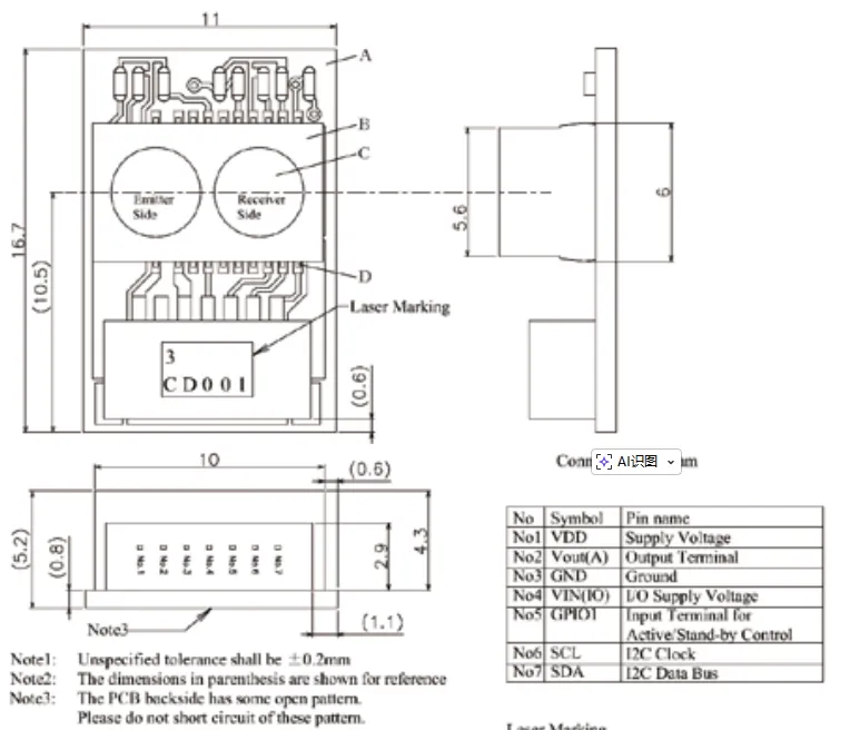
GP2Y0E03 has a total of 7 pins: VDD is the power supply pin, Vout (A) is the analog output terminal, GND is the ground, VIN (IO) is for IO power supply, GPIO1 is the operation/standby control pin, SCL and SDA are I²C clock and data communication pins. The module dimensions are 16.7×11.0×5.2mm, and the pin pitch and dimensional tolerance are ±0.2mm.
2.3 Functional Block Diagram
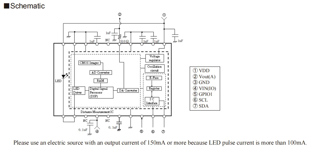
GP2 Y0E03 centers on ranging IC, whose infrared LED emits infrared light that is reflected by the target and then received by the CMOS image sensor; after the signal undergoes AD conversion and DSP processing, it not only outputs an analog voltage signal corresponding to the distance (Vout (A)) via the DA converter, but also outputs digital data through the built-in I²C interface. The VDD and VIN (IO) power supply terminals of the module shall be connected with a decoupling capacitor for filtering;GPIO1 can control the module between working and standby states, and since the pulse current of the LED exceeds 100mA, a power supply with an output current ≥150mA shall be selected for powering the module.
2.4 Performance Parameters
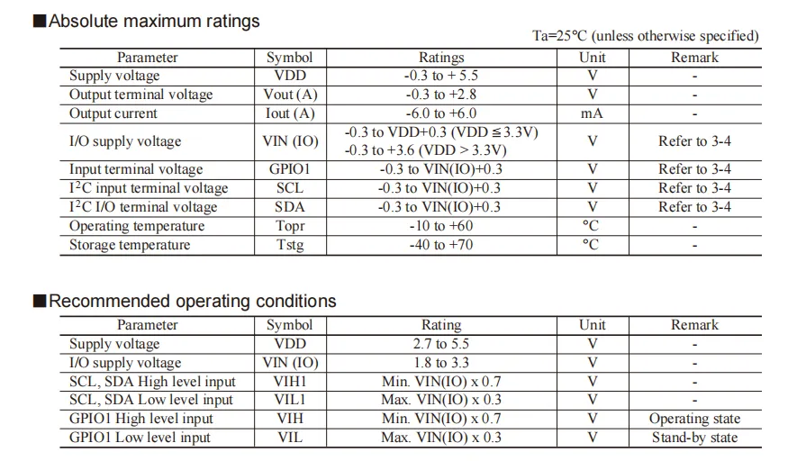
GP2Y0E03 Absolute Maximum Ratings and Recommended Operating Conditions: The power supply voltage ranges from 2.7 V to 5.5 V, I/O power supply voltage ranges from 1.8 V to 3.3 V, the maximum analog output voltage is 2.8 V, and the operating temperature ranges from -10°C to + 60°C;I²C and GPIO pin high and low levels shall be calculated based on the VIN (IO) power supply, GPIO1 high level indicates operating state and low level indicates standby state, and the voltage of all pins shall not exceed the corresponding limit range.
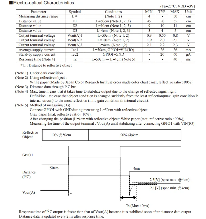
GP2Y0E03 Photoelectric characteristics under the conditions of 25°C and 3V power supply: ranging from 4 to 50 cm; the typical analog output voltages corresponding to the distances of 4 cm, 10 cm and 50 cm are 2.2 V, 2.0 V and 0.55 V respectively; the typical operating current is 26 mA, the standby current is as low as 20 μA, and the maximum response time is 40 ms; the data is measured in a darkroom with high-reflectivity white paper as the test object.
2.5 Reference Circuit
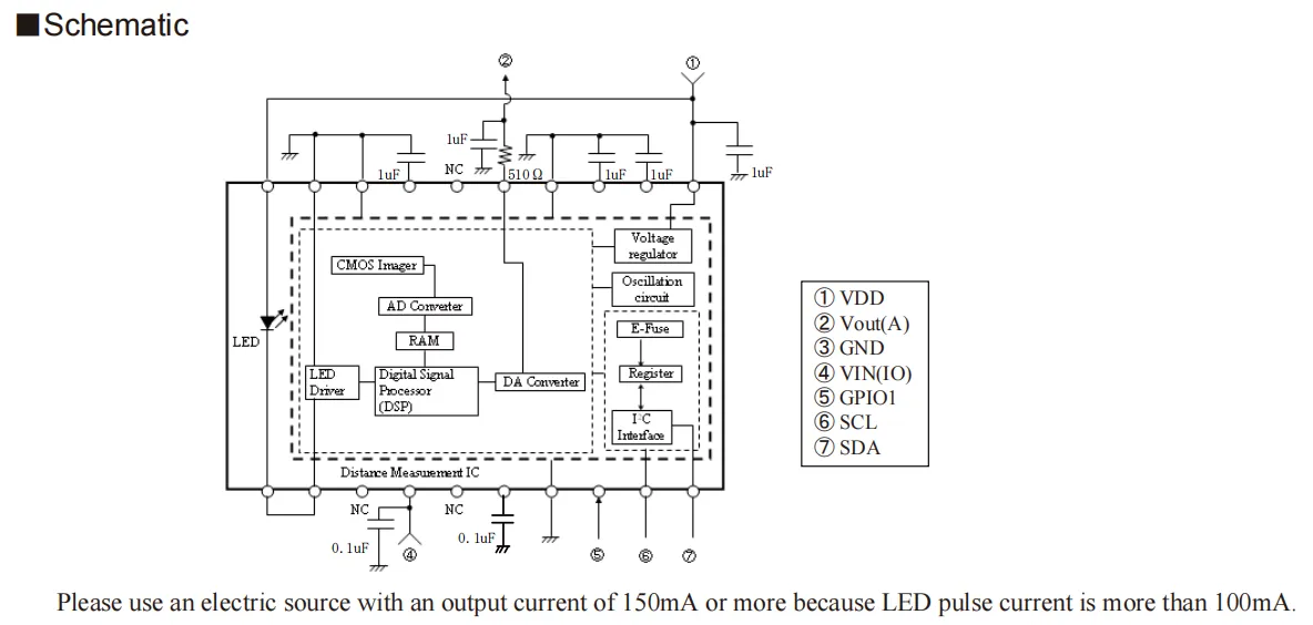
GP2Y0E03 incorporates a built-in infrared LED to emit modulated infrared light, which is reflected by the target and then received by the CMOS image sensor; after the signal undergoes AD conversion and DSP processing, it not only outputs an analog voltage corresponding to the distance via the DA converter (Vout (A)), but also outputs digital data through the I²C interface.Module VDD, VIN (IO) pins are connected with decoupling capacitors for filtering;GPIO1 can control the working/standby status, and since the LED pulse current exceeds 100mA, a power supply with an output current ≥150mA is required.
2.6 Chip Configuration
None.
2.7 Communication Interfaces and Related Protocols
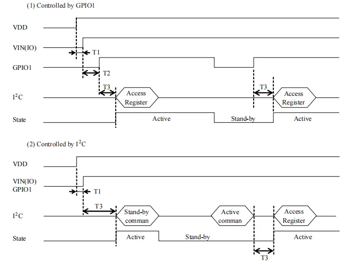
GP2Y0E03 has two working mode control methods: one is controlled by the pin level of GPIO1, pulling it high to enter the working state and pulling it low to enter the standby state; after the state switching, I²C needs to wait for the stabilization time T3 before accessing the registers normally. The other is controlled by I²C commands, sending the corresponding command to switch between the standby and working states, and register access also needs to meet the stabilization time requirement. VDD and VIN (IO) must be powered on in advance to ensure the normal startup of the module.
2.8 PCB Routing Precautions
None.
III. Circuit Engineering
3.1 Circuit Source Engineering
To obtain the source code of the circuit, please follow the official account [Freak Embedded]
3.2 Module Usage Instructions
The schematic diagram of this module is shown below:
SCH_Schematic1_Infrared Distance Sensor Module Based on GP2Y0E03_v1.0.02026-05-08.pdf 2.3 MB
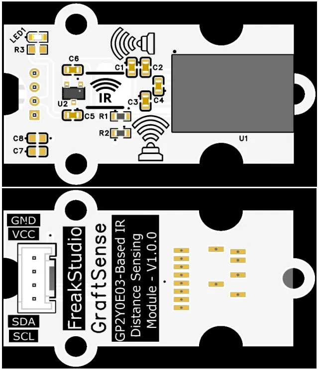
This module provides an IIC communication interface: it supports standard I2C communication rates, is compatible with 3.3V logic level, and can stably transmit the millimeter-level infrared ranging digital signals collected by the GP2Y0E03, which is suitable for distance detection scenarios such as robot obstacle avoidance, position detection, and automatic sensing equipment, providing the system with reliable non-contact distance sensing data interaction capability.
3.3 Application Experiment
Here, we use the GraftPort-RP2040 development board for testing. The GP2Y0E03-based infrared ranging sensor module uses the I2C interface to communicate with the main controller.
Here, we first use the HY2.0-4P cable to connect the module to the GraftPort-RP2040 development board's I2C0 interface:
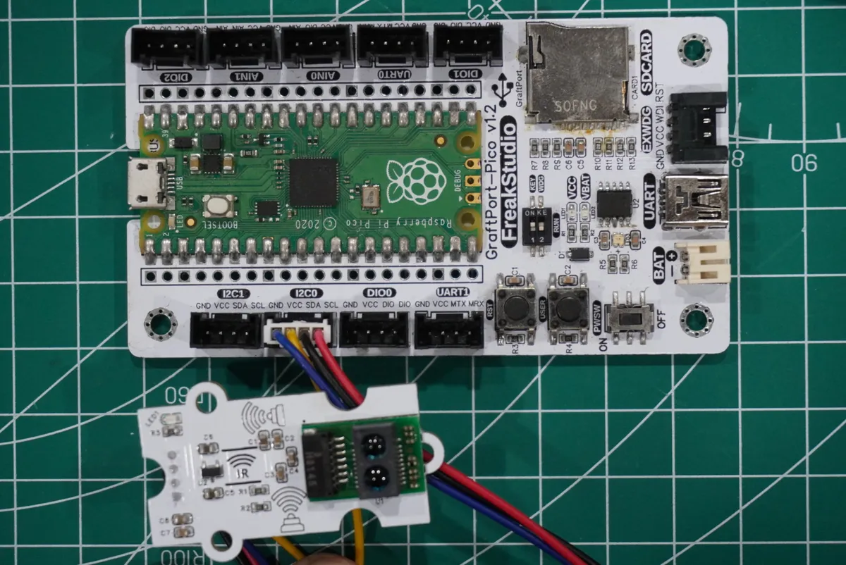
development board pins | Module Pins | Description |
Pin 4 |
|
|
Pin 5 |
|
|
Here, we need to search for the relevant driver packages on uPyPI: https://upypi.net/zh/
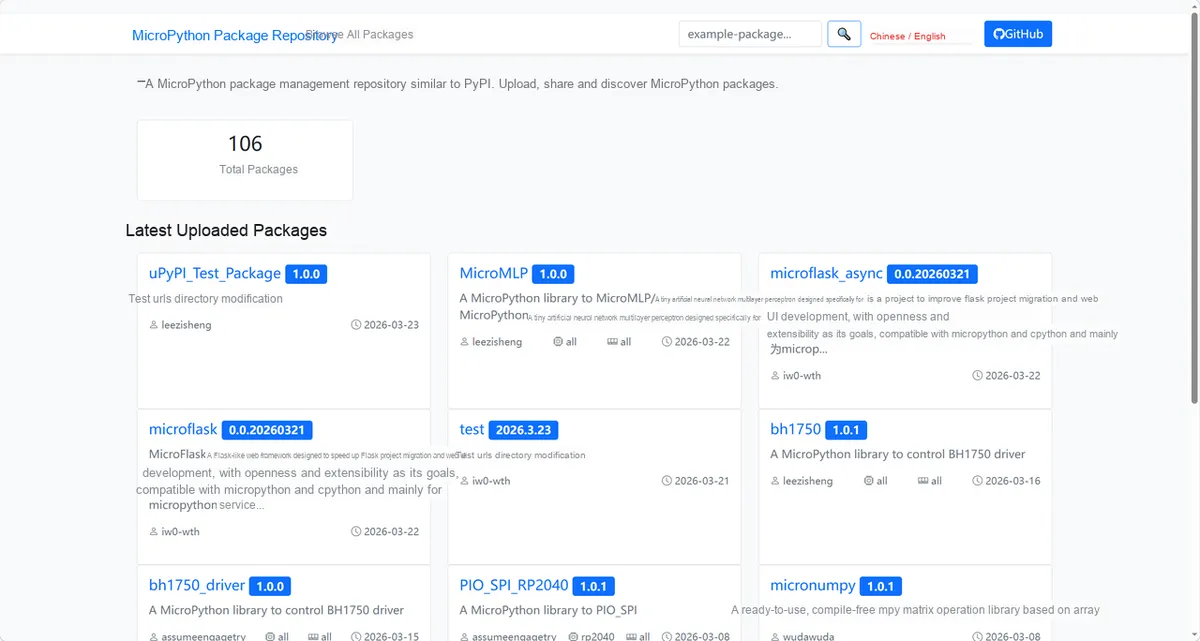
Enter gp2y0e03_driver to search, and the following will be displayed:
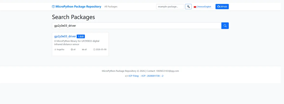
Click to copy the local installation command:
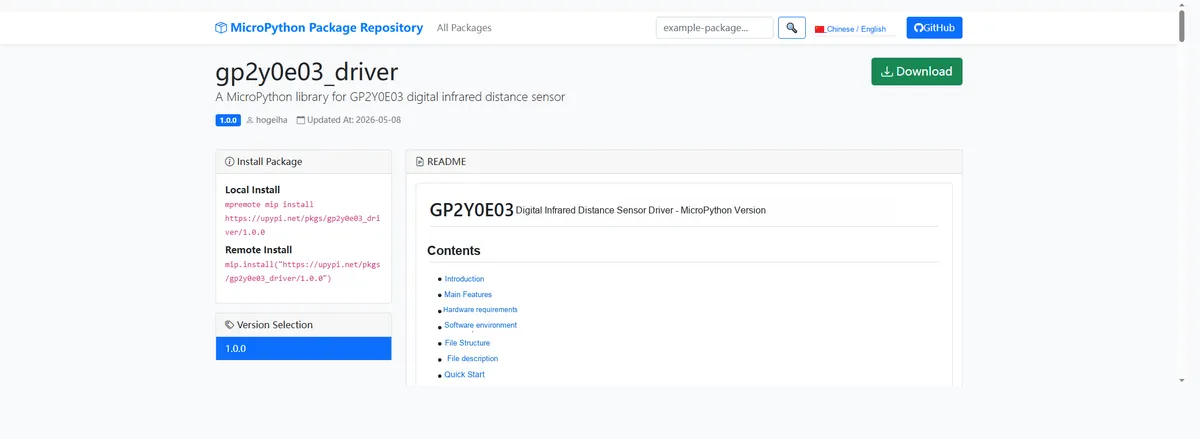
Import the module driver library code via the mip tool. Below are the usage commands for the mpremote tool:
mpremote mip install https://upypi.net/pkgs/gp2y0e03_driver/1.0.0Import the infrared ranging sensor module based on GP2Y0E03 - MicroPython driver code, then copy the following main.py code into our project:
# Python env   : MicroPython v1.23.0
# -*- coding: utf-8 -*-
# @Time    : 2026/04/22 14:15
# @Author  : FreakStudio
# @File    : main.py
# @Description : Test code for the GP2Y0E03 digital infrared distance sensor driver
# @License : MIT


# ======================================== Import Modules =========================================

# Import the MicroPython hardware I2C and pin control modules
from machine import I2C, Pin

# Import the GP2Y0E03 sensor driver class
from gp2y0e03 import GP2Y0E03

# Import the time control module
import time


# ======================================== Global Variables ============================================

# I2C bus number
i2c_id = 0

# I2C data pin number
i2c_sda_pin = 4

# I2C clock pin number
i2c_scl_pin = 5

# I2C communication frequency (Hz)
i2c_freq = 100000

# GP2Y0E03 default I2C address
gp2y0e03_addr = 0x40

# Data print interval (milliseconds)
print_interval = 500

# Timestamp of the last print (milliseconds)
last_print_time = 0


# ======================================== Functions ============================================


# ======================================== Custom Classes ============================================


# ======================================== Initialization ==========================================

# Wait for the system and sensor power to stabilize
time.sleep(3)

# Print the program function prompt
print("FreakStudio: Testing GP2Y0E03 distance sensor driver")

# Initialize the hardware I2C bus
i2c = I2C(
    i2c_id,
    sda=Pin(i2c_sda_pin),
    scl=Pin(i2c_scl_pin),
    freq=i2c_freq,
)

# Scan I2C bus devices
devices = i2c.scan()

# Check whether the scan result is empty
if not devices:
    raise RuntimeError("No I2C devices found on bus")

# Print the I2C device scan result
print("I2C devices found: %s" % [hex(addr) for addr in devices])

# Check whether the GP2Y0E03 is on the I2C bus
if gp2y0e03_addr not in devices:
    raise RuntimeError("GP2Y0E03 not found at address 0x%02X" % gp2y0e03_addr)


# Print the GP2Y0E03 address confirmation
print("GP2Y0E03 found at address: 0x%02X" % gp2y0e03_addr)

# Create the GP2Y0E03 sensor object
sensor = GP2Y0E03(i2c, address=gp2y0e03_addr)

# Print the current distance range shift value
print("Shift: %d" % sensor._shift)


# ========================================  Main Program  ===========================================

try:
    while True:
        # Get the current timestamp
        current_time = time.ticks_ms()

        # Check whether the print interval has elapsed
        if time.ticks_diff(current_time, last_print_time) >= print_interval:
            # Read the raw distance value
            raw = sensor.read(raw=True)

            # Read the distance value in centimeters
            distance = sensor.read()

            # Print the measurement results
            print("Raw: %d, Distance: %.2f cm" % (raw, distance))

            # Update the last print time
            last_print_time = current_time

        # Short delay to avoid excessive CPU usage
        time.sleep_ms(10)

except KeyboardInterrupt:
    print("Program interrupted by user")
except OSError as e:
    print("Hardware communication error: %s" % str(e))
except Exception as e:
    print("Unknown error: %s" % str(e))
finally:
    print("Cleaning up resources...")
    # Release the sensor object
    del sensor
    # Release the I2C object
    del i2c
    print("Program exited")
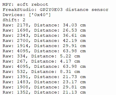
Burn the code, open the terminal, and the output is as follows:
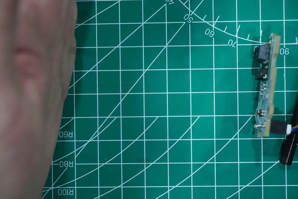
Blocking infrared rays with an object enables distance measurement:
IV. Drivers
gp2y0e03_driver-1.0.0.zip 9 KB
5. BOM & Recommended Alternative Parts
None.
VI. Revision History
Document Version | Date of Revision | Modifier | Modify Content |
v1.0 | 2026-05-08 | Zero High-Luck | Initialize the document |
v1.1 | 2026-06-06 | Xin Ruili | Create an open version of the document based on the internal document version v1.0. |
VII. Relevant Materials
7.1 Chip Datasheet
GP2Y0E03.pdf 747 KB
7.2 Unique Icons for PCB Silk Screen