Contents
- I. Module Introduction
- II. Introduction to Major Chips
- 2.1 Chip Overview
- 2.2 Pin Definition
- 2.3 Functional Block Diagram
- 2.4 Performance Parameters
- 2.5 Reference Circuit
- 2.6 Chip Configuration
- 2.7 Communication Interfaces and Related Protocols
- 2.8 PCB Routing Precautions
- III. Circuit Engineering
- 3.1 Circuit Source Engineering
- 3.2 Module Usage Instructions
- 3.3 Application Experiment
- IV. Drivers
- 5. BOM & Recommended Alternative Parts
- VI. Revision History
- VII. Relevant Materials
- 7.1 Chip Datasheet
- 7.1 Unique Icons for PCB Silk Screen
I. Module Introduction
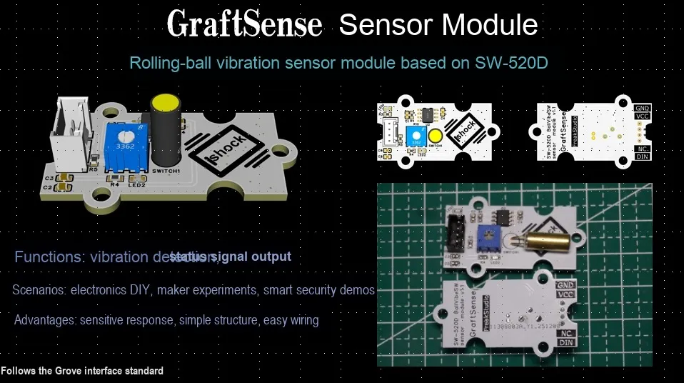
Ball-type vibration sensor module based on SW-520D The core component is SW-520D , a single-directional tilt/vibration detection module based on the ball principle. The core adopts a bimetallic ball design, and the circuit is turned on and off through the rolling contact guide pin of the ball. It is an environmentally friendly device that replaces the traditional mercury switch. Its core characteristics and application scenarios are as follows:
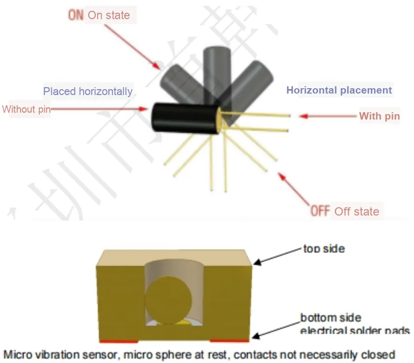
- When the module is subjected to vibration or tilted towards the trigger end, the ball rolls into contact with the guide pin, turning on the circuit and outputting a low level; when tilted towards the cap end, the circuit is disconnected and a high level is output.
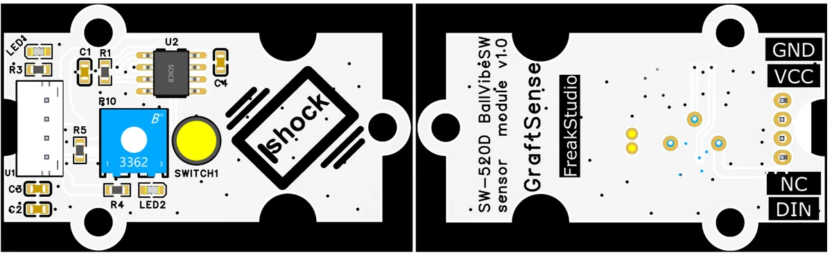
- This module integrates an LM393 comparator and a potentiometer, allowing sensitivity adjustment, delivering stable digital signals, and is also equipped with a vibration indicator to visually show the trigger status.
- It is sealed to be waterproof and dustproof, withstands temperatures ranging from -40°C to 85°C, and has a service life of over 100,000 cycles. It is suitable for scenarios such as security alarms, industrial equipment monitoring, and smart toy posture sensing, and delivers excellent performance in low-current triggering and low-power-consumption devices.
The relationship and working principle among vibration switches, ball switches and spring switches:
Vibration switch is a general term, which is mainly divided into two categories in the industry: spring switches and ball switches. A spring switch realizes the on-off of the circuit through the deformation of its internal spring caused by vibration force to contact with or separate from the pins, which is suitable for vertical installation and focuses on detecting the magnitude of vibration force. A ball switch makes the metal ball roll to conduct the circuit through angle change, which is suitable for flat installation and focuses on detecting the tilt angle. The two together constitute a vibration sensing element that converts vibration or angle signals into electrical signals by means of mechanical structure displacement.
Common vibration switches SW series fall into two categories:
SW-18xxxSpring-loaded vibration switches (e. g.,SW-18010P,SW-18015P, etc.):- Inside the component, there is a thin metal spring and a central electrode, which are separated under normal conditions; when vibration occurs, the spring shakes to come into contact with the electrode, thus realizing on/off switching.
- Features: High sensitivity, capable of detecting slight vibrations, but prone to generating jitter signals.
SW-20xxBall-type vibration switches (e. g.,SW-200D,SW-200DR, etc.):- Inside the device, there is a small metal ball placed in a cylinder; when subjected to vibration, the ball moves to come into contact with the electrode.
- Features: Relatively low sensitivity, but more stable triggering and better anti-jitter performance.
👉 So the SW-18010P you asked about belongs to the spring-switch type vibration sensor.
This section of knowledge is referenced from: Understanding the Relationship and Working Principles Among Vibration Switches, Ball Switches, and Spring Switches.
II. Introduction to Major Chips
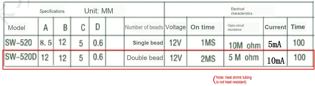
This module mainly relies on SW-520D bimetal ball type vibration/tilt induction trigger switch to realize signal changes.
2.1 Chip Overview
2.2 Pin Definition
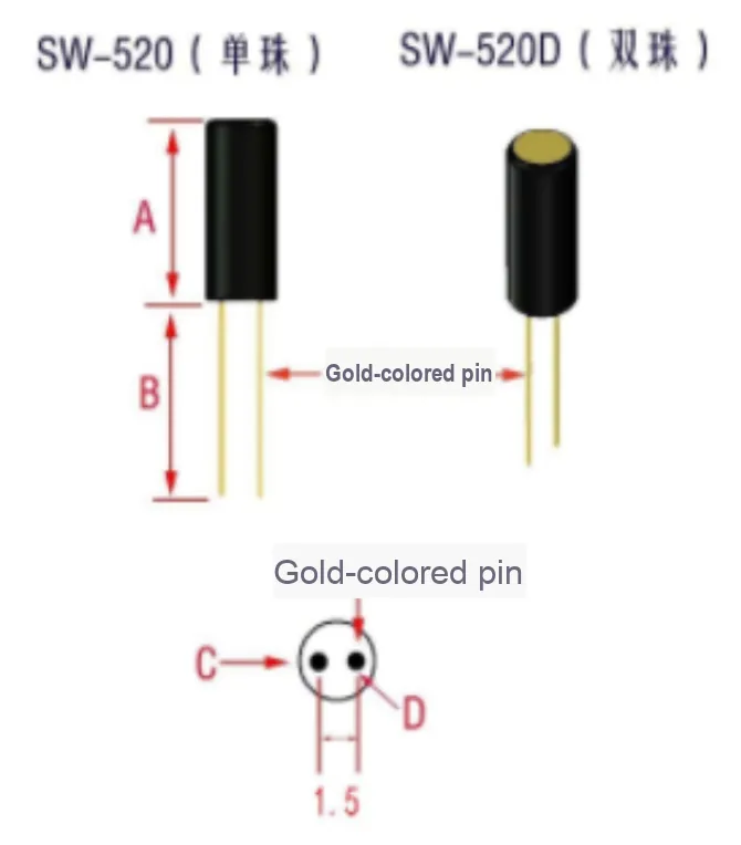
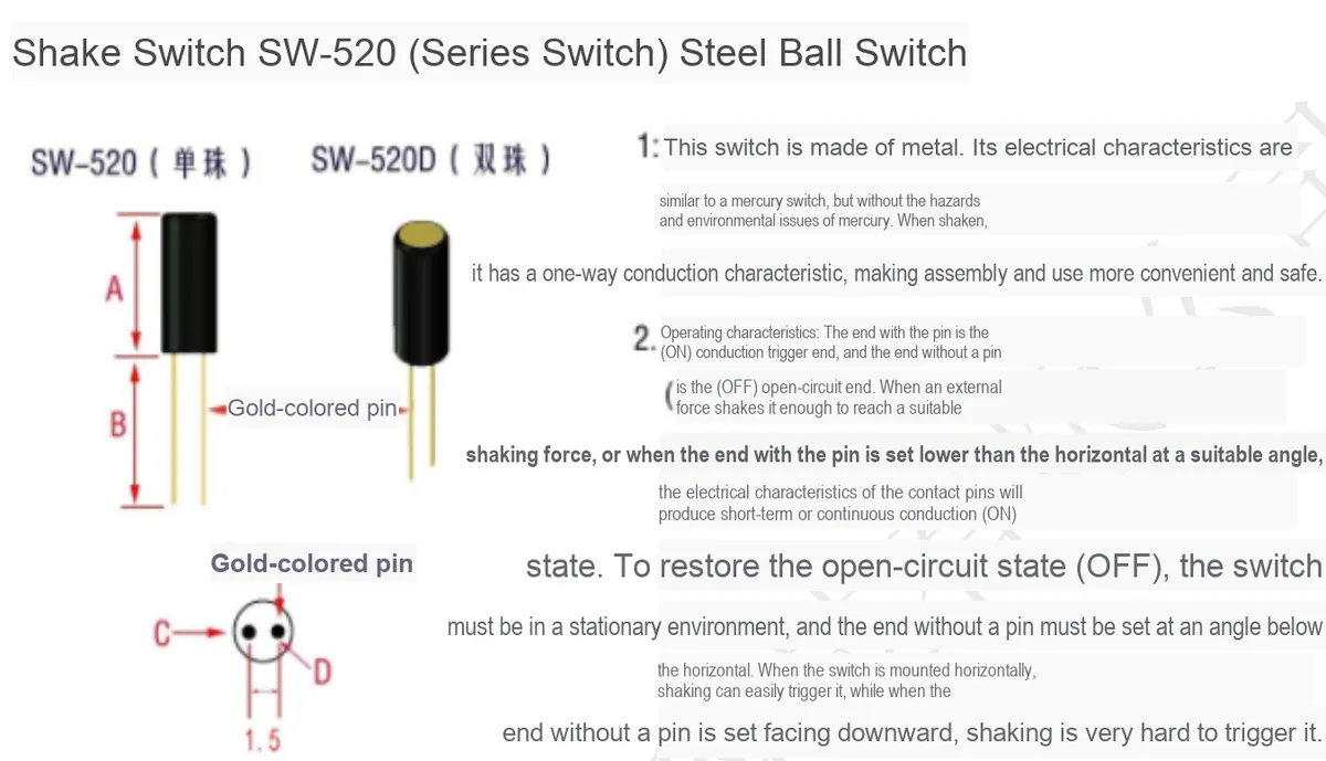
SW-520 (single bead) and SW-520D (double beads) both feature a 2-pin plug-in structure. The bottom view shows two gold-colored conductive pins arranged in parallel with a spacing of approximately 1.5mm:
- Pin Function: There is no strict distinction between "input" and "output". The on/off state of the two pins is realized through the rolling of the internal ball: when the ball contacts the two guide pins, the circuit is conductive (low resistance); when the ball moves away, the circuit is disconnected (high resistance).
- Installation and Wiring: In practical use, simply connect the two pins to the "signal terminal" and "ground terminal (or power terminal)" of the circuit respectively. The mechanical displacement of the ball is used to control the on-off of the loop, and there is no need to distinguish the polarity of the pins.
This symmetrical non-polarity design enables more flexible installation and is suitable for automated control in scenarios such as inclination and vibration.
2.3 Functional Block Diagram
None.
2.4 Performance Parameters
2.5 Reference Circuit
2.6 Chip Configuration
None
2.7 Communication Interfaces and Related Protocols
None.
2.8 PCB Routing Precautions
None.
III. Circuit Engineering
3.1 Circuit Source Engineering
To obtain the source project of the circuit, please follow the official account [Freak Embedded]
3.2 Module Usage Instructions
The schematic diagram of this module is shown below:
SCH_Ball-Type Vibration Sensor Module Based on SW-520D_v1.0_2025-09-21.pdf 2.8 MB
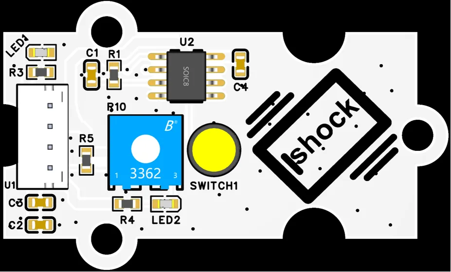
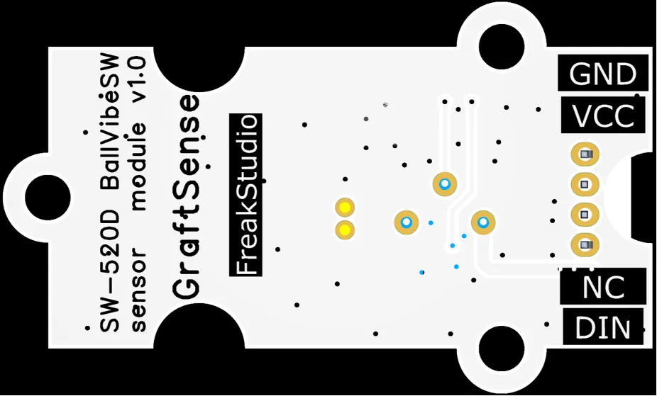
This module uses digital output DIN: when stationary DIN outputs a high level, and when vibrating DIN outputs a low level.
It also features a dual-indicator design: the power indicator (LED1) staying on indicates the module is powered on; the vibration indicator (LED2) being on indicates vibration is detected.
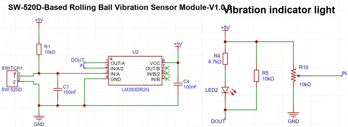
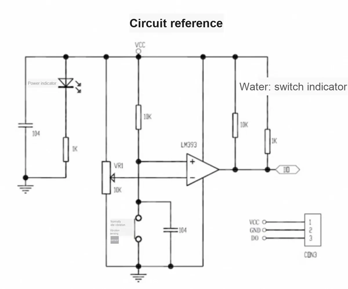
The module takes SW-520D as the core, and cooperates with components such as the voltage comparator LM393, indicator light, filter capacitor, etc. , to convert mechanical vibration into a stable electrical signal output. The overall circuit is divided into the following parts:
- SW-520D Core Circuit:
- Power Supply and Filtering: The + 5V power supply is current-limited via
R1(10kΩ), with one branch connected to one end ofSW-18010P, and the other branch grounded after being filtered viaC1(100nF); - Comparator LM393: compares the conduction signal (low level) from
SW-520Dwith the reference voltage, and outputs a clean digital signal (DOUT); - Sensitivity Adjustment: Potentiometer
R10(10kΩ) can fine-tune the threshold of the comparator to control the sensitivity of vibration triggering.
- Power Supply and Filtering: The + 5V power supply is current-limited via
- Vibration indicator circuit: When
DOUToutputs a low level,LED2(in series withR4= 4.7kΩ) lights up to visually indicate the vibration trigger status;
3.3 Application Experiment
Here, we use the GraftPort-RP2040 development board for testing, and connect the ball-type vibration sensor module based on SW-520D to communicate with the main controller via the DIO interface.
Here, we first use the HY2.0-4P connection cable to connect the module to the GraftPort-RP2040 development board's DIO0 interface:
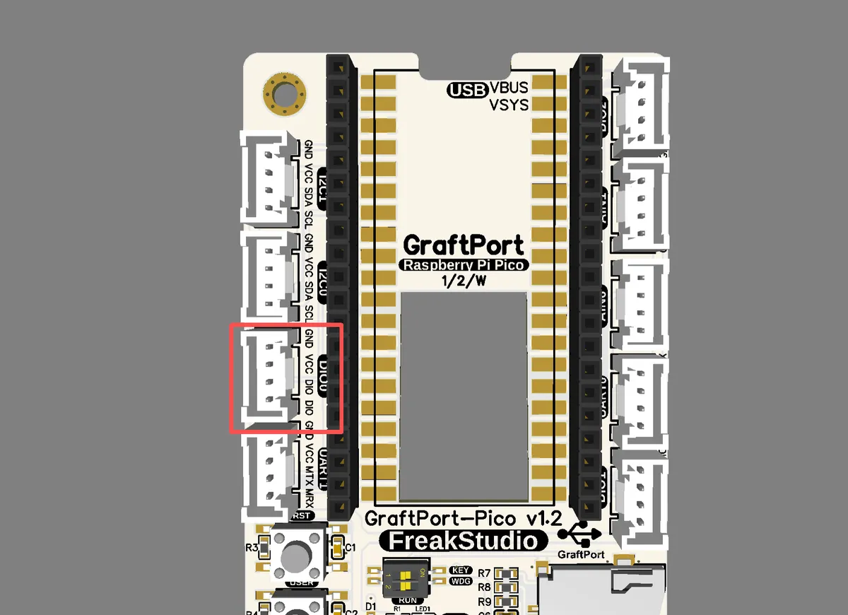
The module connections are shown in the following table:
Development Board Pins | Module Pins | Description |
Pin 6 |
| Sensor level signal input pin |
Pin 7 |
| - |
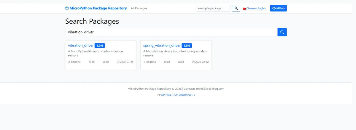
Here, we need to search for the relevant driver packages on uPyPI: https://upypi.net/zh/
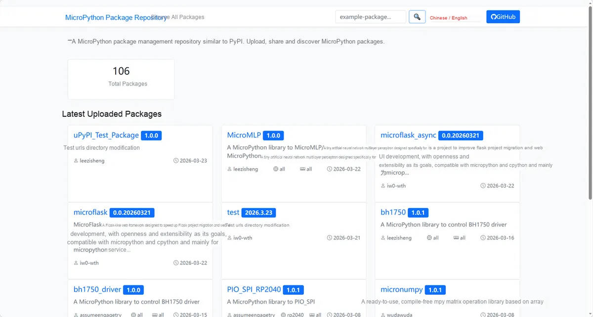
Enter vibration_driver to search, and the following will be displayed:
Click to copy the local installation command:
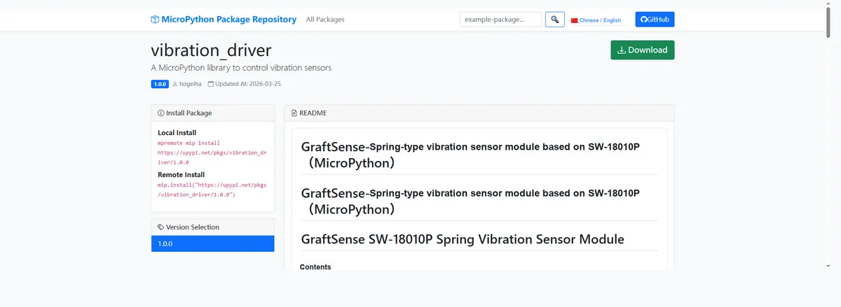
Here, we can use the mip tool to import module driver library code. The following are the usage commands for the mpremote tool:
mpremote mip install github:FreakStudioCN/GraftSense-Drivers-MicroPython/sensors/vibration_driverAfter importing the vibration sensor module - MicroPython driver code, copy the following main.py code into our project:
# MicroPython v1.23.0
# -*- coding: utf-8 -*-
# @Time    : 2025/8/23 PM 4:08
# @Author  : 缪贵成
# @File    : main.py
# @Description : Rolling ball vibration sensor driver test file

# ======================================== Import Related Modules ==========================================

import time
from machine import Pin
from vibration_sensor import VibrationSensor

# ======================================== Global Variables =============================================

# ======================================== Functions ==============================================

def vibration_callback() -> None:
    """
    Vibration callback function, triggered when vibration is detected.

    Notes:
        This function is triggered by an interrupt and scheduled for execution through micropython.schedule.

    ==========================================

    Vibration callback function, triggered when vibration is detected.

    Notes:
        This function is called from interrupt, scheduled via micropython.schedule.
    """
    print("Vibration detected callback triggered!")

# ======================================== Custom Classes =============================================

# ======================================== Initialization Configuration ============================================

# Power-up delay to ensure hardware stability
time.sleep(3)
print("FreakStudio: Vibration Sensor Test Start")
# Initialize the vibration sensor, GPIO pin 6 as input, handled by the callback function
sensor = VibrationSensor(pin=Pin(6), callback=vibration_callback, debounce_ms=10)
sensor.init()
print("Sensor initialized with callback and debounce 50ms.")

# ======================================== Main Program ===============================================

try:
    start_time = time.ticks_ms()
    while True:
        # Poll to read the sensor status
        current_state: bool = sensor.read()
        print(f"Current vibration state: {current_state}")

        # Print the status dictionary every 2 seconds
        if time.ticks_diff(time.ticks_ms(), start_time) > 2000:
            status: dict = sensor.get_status()
            print(f"Sensor status: {status}")
            start_time = time.ticks_ms()

        time.sleep(0.2)

except KeyboardInterrupt:
    # Exit on user interrupt
    print("KeyboardInterrupt detected. Exiting test...")

finally:
    # Safely release resources
    sensor.deinit()
    print("Sensor deinitialized. Test completed.")
Burn the code, open the terminal, and use the mpremote tool to connect to the main controller. The output is as follows:
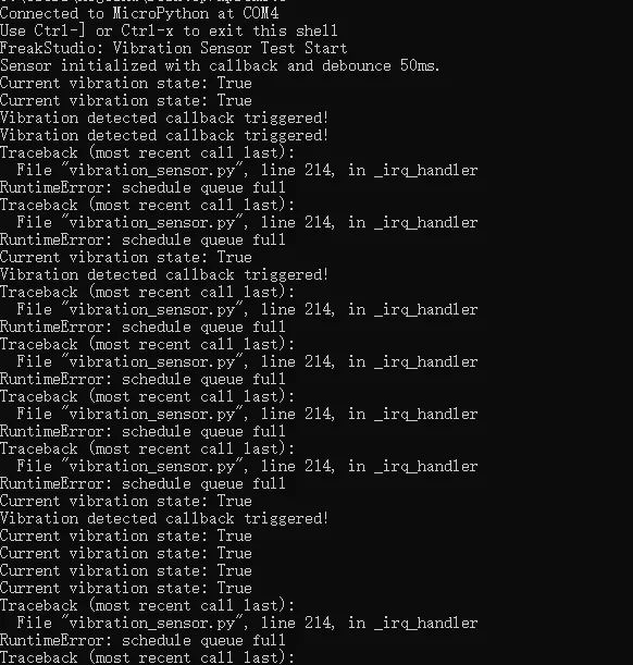
As you can see, when we shake the sensor by hand, the relevant interrupt callback function will be triggered continuously:
IV. Drivers
vibration_driver.zip 10 KB
5. BOM & Recommended Alternative Parts
None.
VI. Revision History
Document Version | Date of Modification | Modifier | Modified Content |
v1.0 | 2025-09-21 | Li Zisheng | Initialize the document The BOM sheet has not been finally checked, the driver has not been re-verified, and the 3.3 application experiment Not yet specified. |
v1.1 | 2025-12-29 | Li Zisheng | Added application experiments and production files |
v1.2 | 2025-12-31 | Xin Ruili | Create an open version of the document based on the internal document version v1.1. |
v1.3 | 2026-03-29 | Xin Ruili | Modified the application experiment section |
VII. Relevant Materials
7.1 Chip Datasheet
C5379904_Vibration Sensor_SW-520D_Datasheet_SW-520D.PDF 1.7 MB
7.1 Unique Icons for PCB Silk Screen