Contents
- I. Module Introduction
- II. Introduction to Main Chips
- 2.1 Chip Overview
- 2.2 Pin Definition
- 2.3 Functional Block Diagram
- 2.4 Performance Parameters
- 2.5 Reference Circuit
- 2.6 Chip Configuration
- 2.7 Communication Interfaces and Related Protocols
- 2.8 PCB Routing Notes
- III. Circuit Engineering
- 3.1 Circuit Source Engineering
- 3.2 Module Usage Instructions
- 3.3 Application Experiment
- IV. Drivers
- 5. BOM & Recommended Alternative Parts
- 6. Revision History
- VII. Relevant Materials
- 7.1 Chip Datasheet
- 7.2 Unique Icons for PCB Silk Screen
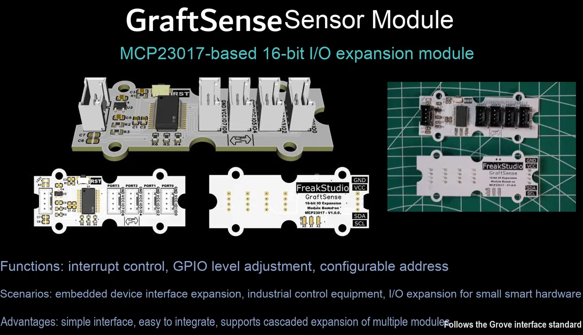
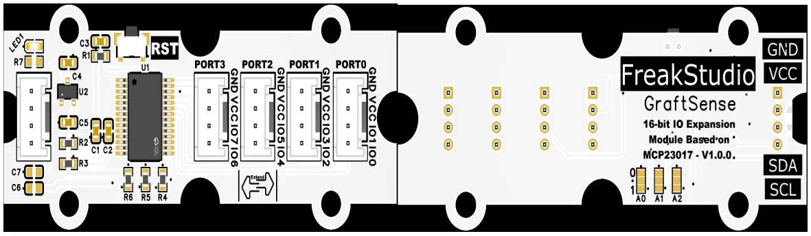
I. Module Introduction
16-bit IO expansion module based on MCP23017, which adopts the MCP23017 chip solution, provides 16 independently configurable digital input/output ports for MCU via the I²C bus, supports high-speed communication up to 1.7Mbps, is equipped with a 3.3V LDO voltage regulator and power filtering circuit, and realizes cascading of up to 8 devices through the address dip switches of A0 / A1 / A2, which can be expanded to 128 GPIO ports. It is compatible with 3.3V level MCUs, and is suitable for scenarios such as embedded control, sensor acquisition and industrial automation where IO port resources are insufficient.
Note: Considering the size of the module and actual usage scenarios, only 8 IO expansion pins are led out here!!!
II. Introduction to Main Chips
MCP23017 is a Microchip -launched 16-bit I²C interface GPIO expansion chip. It has two built-in 8-bit port registers, supports a maximum communication rate of 1.7Mbps, and enables multi-device cascading via address pins, providing flexible digital MCU with flexible digital IO expansion capabilities.
2.1 Chip Overview
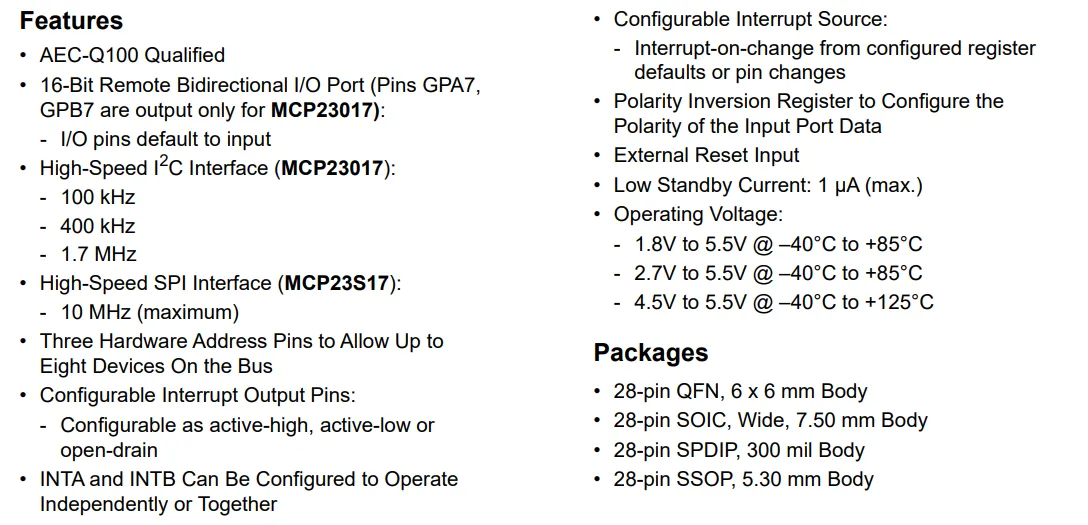
MCP23017 features cover 16-bit bidirectional I/O ports, up to 1.7MHz high-speed I²C interface, 3-bit hardware address pins (supporting cascade of up to 8 devices), configurable interrupt and polarity inversion, as well as 1.8V~5.5V wide voltage power supply and multiple package options, and it also has AEC-Q100 automotive certification and low standby current characteristics.
2.2 Pin Definition
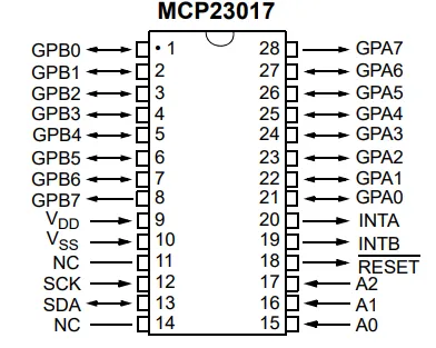
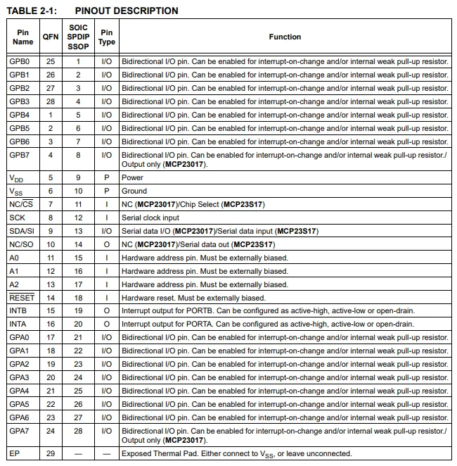
The pinout and pin function table of the MCP23017 clearly specify the functions and types of the 16-bit bidirectional I/O ports (GPA0 ~ GPA7, GPB0 ~ GPB7), I²C communication pins (SDA / SCK), address selection pins (A0 / A1 / A2), interrupt output pins (INTA / INTB) and reset/power pins, providing accurate pin definition reference for hardware design and driver development.
2.3 Functional Block Diagram
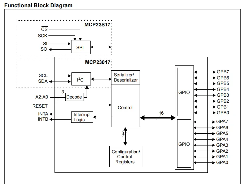
MCP23017 receives commands and data internally via the I²C interface; after address decoding, the Control Unit coordinates to write configurations into the 8-bit control register bank, and then completes bidirectional mapping between data and 16-channel GPIO ports through a serializer/deserializer. Meanwhile, the interrupt logic module processes interrupt requests triggered by level changes, ultimately enabling the MCU to perform input/output, interrupt and parameter configuration for 16 independent digital IO channels, providing the system with stable IO expansion and status feedback capabilities.
2.4 Performance Parameters
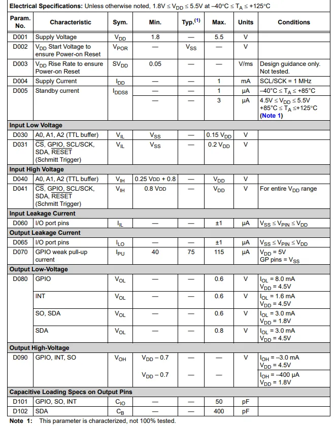
MCP23017 electrical characteristic parameter table covers the supply voltage range (1.8V~5.5V), standby current (max. 3μA), input high and low level thresholds, GPIO leakage current and pull-up current, output drive capability and capacitive load limit and other key electrical indicators, providing accurate parameter basis for hardware circuit design and reliability evaluation.
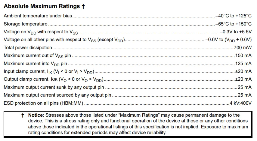
MCP23017 's absolute maximum ratings table specifies the device' s tolerance limits under extreme conditions, including operating/storage temperature range, voltage limits for each pin, total power consumption and pin current upper limits as well as ESD protection level, and warns that exceeding the rated values will cause permanent damage, providing a key reference for the safety margin and reliability protection of hardware design.
2.5 Reference Circuit
None.
2.6 Chip Configuration
None.
2.7 Communication Interfaces and Related Protocols
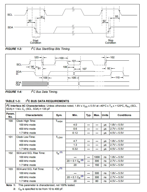
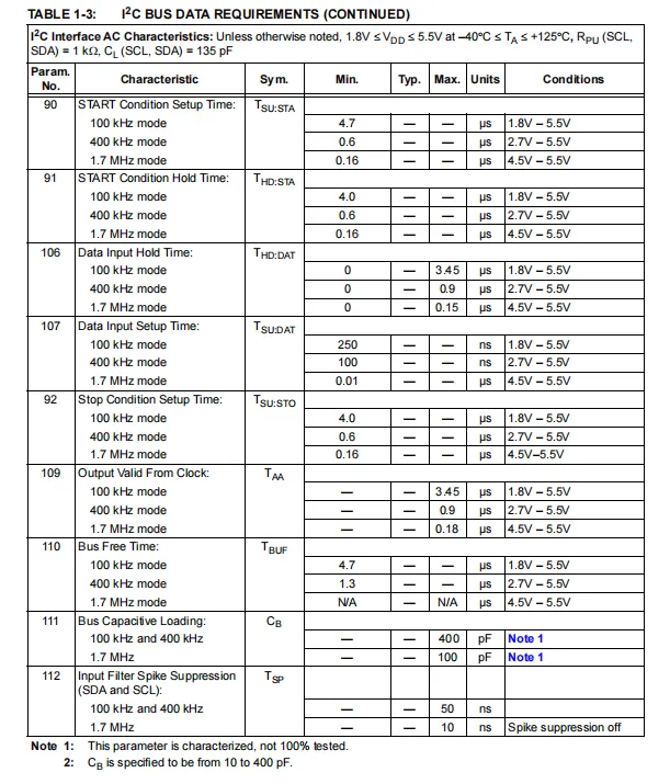
MCP23017 I²C interface Sequence Diagram and AC electrical parameter table define in detail the start/stop condition timing, data read/write timing, as well as key timing parameters such as clock high/low level, rise/fall time, setup/hold time under the three communication modes of 100kHz/400kHz/1.7MHz. It also specifies the bus capacitive load range, providing precise timing constraints for the stable and reliable implementation of I²C communication.
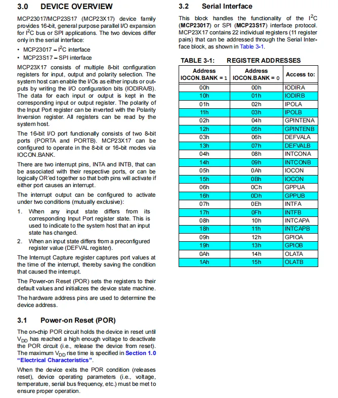
MCP23017 device overview and register address table introduces its 16-bit bidirectional I/O expansion function, I²C interface features, configurable interrupt mechanism and power-on reset logic, and lists the address mapping of all registers, covering configuration registers such as direction, polarity, interrupt, pull-up and output latch, providing a clear instruction format reference for driver development and register operation.
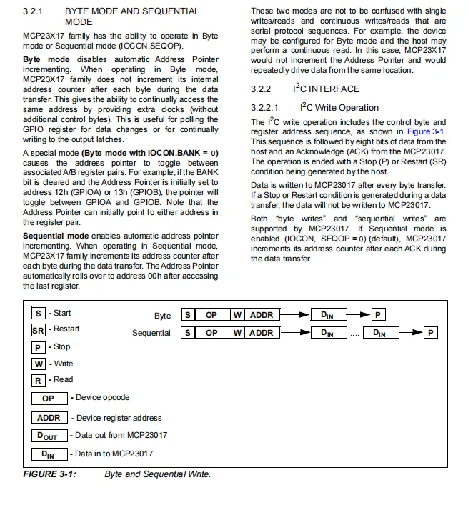
MCP23017 's Byte Mode and Sequential Mode, which describes two I²C data transmission modes: Byte Mode disables the auto-increment of the address pointer, allowing repeated access to the same register; Sequential Mode enables automatic increment of the address pointer, supporting continuous read and write operations on multiple sets of registers. Meanwhile, the Sequence Diagram for the write operation of both modes is also provided.
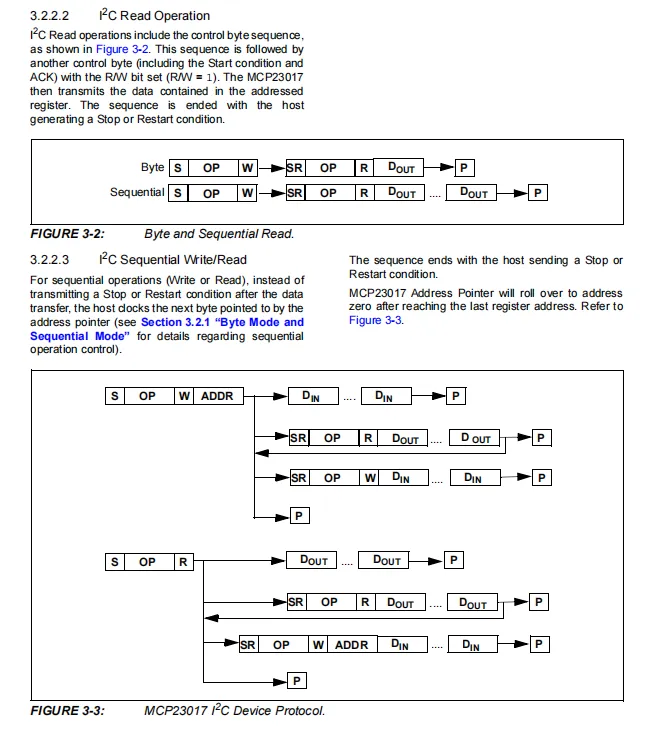
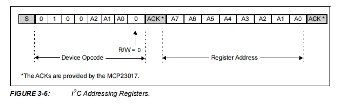
MCP23017 I²C read operations and complete Communication Protocol, byte/sequential read mode timing sequence, sequential read-write composite operation address pointer auto-increment logic, as well as I²C register addressing format (device opcode + register address), provide a clear protocol process reference for efficient batch register read-write and multi-device communication.
2.8 PCB Routing Notes
None.
III. Circuit Engineering
3.1 Circuit Source Engineering
To obtain the circuit source project, please follow the official account [Freak Embedded].
3.2 Module Usage Instructions
SCH_16-bit IO Expansion Module Based on MCP23017-V1.0.0_2026-03-27.pdf 2.3 MB
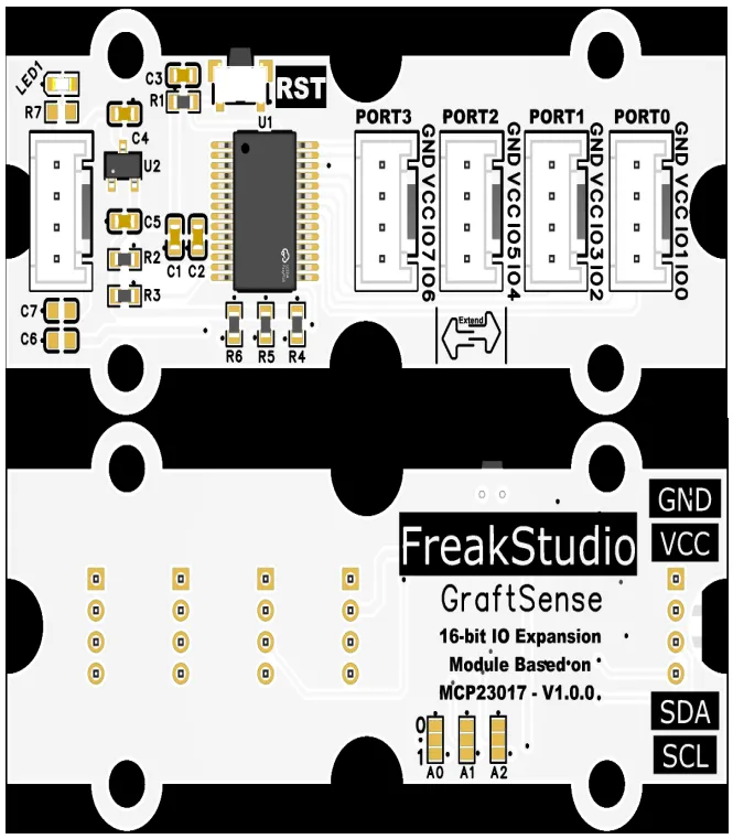
This module provides an I²C communication interface, which supports three communication modes: standard (100kbps), fast (400kbps) and high-speed (1.7Mbps). The device address can be flexibly configured via the A0 / A1 / A2 address dip switches (e. g., 0x20, 0x22, etc.), and supports cascading of up to 8 devices to expand to 128 channels of GPIO. It is compatible with 3.3V level, and can stably realize the direction configuration, level read/write and interrupt status reading of 16 channels of digital IO. It is suitable for scenarios such as embedded control, sensor acquisition and industrial automation where MCU IO port resources are insufficient, providing the system with efficient and stable digital IO expansion and interaction capabilities. Meanwhile, in case of occasional chip failure, you can press the RST button to reset.
Note: Considering the size of the module and actual usage scenarios, only 8 IO expansion pins are led out here!!!
IO For common usage scenarios of the expansion module, please refer to the following document:
3.3 Application Experiment
Here, we use the GraftPort-RP2040 development board for testing, and the 16-bit IO expansion module based on MCP23017 uses the I2C interface to communicate with the main controller.
Here, we first use the HY2.0-4P cable to connect the module to the I2C0 interface of the GraftPort-RP2040 development board, and short the PORT1 and PORT0 interfaces using the HY2.0-4P cable:
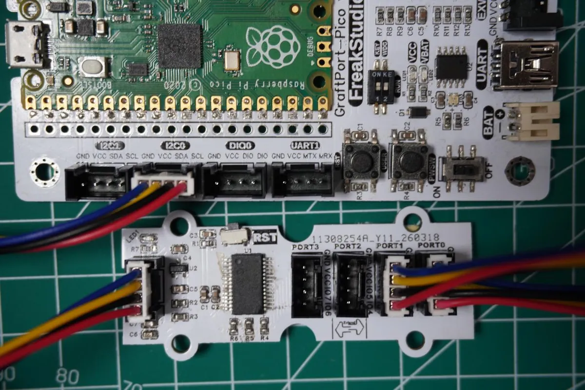
The module connections are shown in the following table:
Development Board Pins | Module Pins | Description |
Pin 4 |
|
|
Pin 5 |
|
|
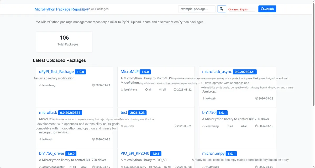
Here, we need to search for the relevant driver packages on uPyPI: https://upypi.net/zh/
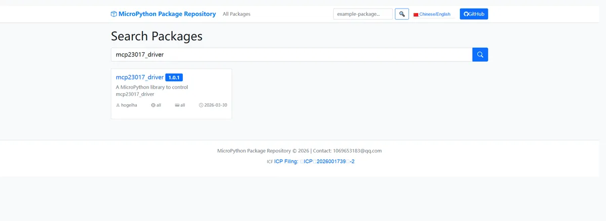
Enter mcp23017_driver to search, and the following will be displayed:
Click to copy the local installation command:
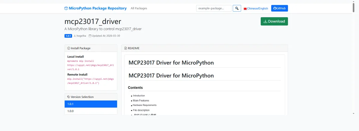
Import the module driver library code via the mip tool. Below are the usage commands for the mpremote tool:
mpremote mip install https://upypi.net/pkgs/mcp23017_driver/1.0.0Import the 16-bit IO expansion module based on MCP23017 - MicroPython driver code, then copy the following main.py code into our project:
# Python env   : MicroPython v1.23.0
# -*- coding: utf-8 -*-
# @Time    : 2026/3/13 6:20 PM
# @Author  : hogeiha
# @File    : main.py
# @Description : MCP23017 test  Configure I2C scan, pin input/output, virtual pin operations, input polarity inversion verification

# ======================================== Import Modules =========================================

from machine import SoftI2C, Pin
import mcp23017  # Import the MCP23017 driver module
import time

# ======================================== Global Variables ============================================

# I2C hardware configuration constants
I2C_SCL_PIN = 5
I2C_SDA_PIN = 4
I2C_FREQ = 100000
# MCP23017 target I2C address
TARGET_SENSOR_ADDR = 0x20
# Pin definition constants
A1_PIN = 1  # A1 pin number (output)
A3_PIN = 3  # A3 pin number (input)
# Global MCP23017 object
mcp = None

# ======================================== Functions ============================================


def test_mcp_functions():
    """
    Demonstrate the core MCP23017 functions: basic level read/write, virtual pin operations, batch register operations, input polarity inversion
    Args:
        None

    Raises:
        None

    Notes:
        Verify the different function modules in turn and output key debug information

    ==========================================

    Demonstrate MCP23017 core functions: basic level read/write, virtual pin operation, batch register operation, input polarity inversion
    Args:
        None

    Raises:
        None

    Notes:
        Verify different function modules in sequence and output key debugging information
    """
    # ---------- Demo 1: Basic read/write (A3 output, A3 read) ----------
    print("\n=== Demo 1: Basic Level Read/Write ===")
    # Switch the A3 level to high and read A3 to verify (after shorting, A3 should follow high)
    mcp.pin(A1_PIN, value=1)
    a3_val = mcp.pin(A3_PIN)  # Read the A3 level (returns True/False)
    print(f"A3 Output Level: HIGH (1) | A3 Read Level: {'HIGH (1)' if a3_val else 'LOW (0)'}")

    # Switch the A3 level to low and read A3 to verify
    mcp.pin(A1_PIN, value=0)
    a3_val = mcp.pin(A3_PIN)
    print(f"A3 Output Level: LOW (0) | A3 Read Level: {'HIGH (1)' if a3_val else 'LOW (0)'}")

    # ---------- Demo 2: Virtual pin usage (more intuitive pin operations) ----------
    print("\n=== Demo 2: Virtual Pin Operation ===")
    # Get the virtual pin objects for A3 and A3
    A3_vpin = mcp[A1_PIN]
    a3_vpin = mcp[A3_PIN]

    # Set A3 high using the virtual pin
    A3_vpin.output(val=1)  # Equivalent to mcp.pin(A1_PIN, mode=0, value=1)
    a3_val = a3_vpin.value()  # Read the A3 level
    print(f"Virtual Pin A3 Output: HIGH (1) | Virtual Pin A3 Read: {'HIGH (1)' if a3_val else 'LOW (0)'}")

    # ---------- Demo 3: Batch configure/read registers (advanced) ----------
    print("\n=== Demo 3: Batch Register Operation ===")
    # Read the overall mode of PortA (A0-A7) (IODIR register)
    porta_mode = mcp.porta.mode
    print(f"PortA Mode Register Value: 0x{porta_mode:02X} (A3=Output(0), A3=Input(1) As Expected)")

    # Read the pull-up resistor configuration of PortA (GPPU register)
    porta_pullup = mcp.porta.pullup
    print(f"PortA Pullup Register Value: 0x{porta_pullup:02X} (A3 Pullup Enabled(1) As Expected)")

    # ---------- Demo 4: Input polarity inversion (optional, uncomment to verify) ----------
    print("\n=== Demo 4: Input Polarity Inversion ===")
    # Enable A3 polarity inversion
    mcp.pin(A3_PIN, polarity=1)
    # Set A3 high again; A3 read should be low (because of polarity inversion)
    mcp.pin(A1_PIN, value=1)
    a3_val = mcp.pin(A3_PIN)
    print(f"A3 Output: HIGH (1) | A3 Inverted Read: {'HIGH (1)' if a3_val else 'LOW (0)'} (Expected LOW)")

    # Restore A3 polarity to normal
    mcp.pin(A3_PIN, polarity=0)


def loop_verify():
    """
    Loop to verify level synchronization between the A3 output and the A3 input, toggling the A3 level every 1 second
    Args:
        None

    Raises:
        None

    Notes:
        Loop 5 times and output the level match result each time; A3 and A3 pins must be shorted together

    ==========================================

    Cyclically verify the level synchronization between A3 output and A3 input, switch A3 level every 1 second
    Args:
        None

    Raises:
        None

    Notes:
        Loop 5 times, output the level matching result each time, need to short-circuit A3 and A3 pins
    """
    print("\n=== Loop Verification (Switch A3 Level Every 1 Second) ===")
    print("Short-circuit A3 and A3, observe if A3 synchronizes with A3 level changes...")
    count = 0
    while count < 5:  # Loop 5 times
        # Toggle the A3 level
        current_val = count % 2  # Alternate 0/1
        mcp.pin(A1_PIN, value=current_val)
        # Read A3
        a3_val = mcp.pin(A3_PIN)
        # Print the result
        print(f"Round {count+1} - A3 Output: {current_val} | A3 Read: {1 if a3_val else 0} | Matched: {current_val == a3_val}")
        time.sleep(1)
        count += 1


# ======================================== Custom Classes ============================================


# ======================================== Initialization configuration ===========================================

time.sleep(3)
print("FreakStudio: MCP23017 I2C Expander Function Test - Short A3 and A3 Pins")

# Initialize the I2C bus (for Raspberry Pi Pico)
i2c_bus = SoftI2C(scl=Pin(I2C_SCL_PIN), sda=Pin(I2C_SDA_PIN), freq=I2C_FREQ)

# Start scanning for devices on the I2C bus
devices_list: list[int] = i2c_bus.scan()
print("START I2C SCANNER")

# Check the I2C device scan result
if len(devices_list) == 0:
    print("No i2c device !")
    raise SystemExit("I2C scan found no devices, program exited")
else:
    print("i2c devices found:", len(devices_list))

# Iterate over the address list to initialize the target sensor (MCP23017)
for device in devices_list:
    if device == TARGET_SENSOR_ADDR:
        print("I2c hexadecimal address:", hex(device))
        try:
            # Initialize MCP23017
            mcp = mcp23017.MCP23017(i2c=i2c_bus, address=TARGET_SENSOR_ADDR)
            print("Target sensor initialization successful")
            break
        except Exception as e:
            print(f"Sensor Initialization failed: {e}")
            continue
else:
    # Raise a clear exception when the target address is not found
    raise Exception("No MCP23017 found at target address 0x20")

# Configure pins (core: A3 output, A3 input)

# Configure A3 as output mode (mode=0), initial level low (value=0)
mcp.pin(A1_PIN, mode=0, value=0)
# Configure A3 as input mode (mode=1), enable internal pull-up resistor (pullup=1)
mcp.pin(A3_PIN, mode=1, pullup=1)

# ========================================  Main Program  ============================================

if __name__ == "__main__":
    try:
        # Run the core function test
        test_mcp_functions()
        # Run the loop verification
        loop_verify()
        print("\nProgram execution completed successfully!")
    except OSError as e:
        print(f"Error: {e}, Please check I2C wiring or MCP23017 address!")
    except Exception as e:
        print(f"Initialization Error: {e}")
In the above code, we set the A1 pin as output, the A3 pin as input, and short the two pins together. We then test the chip's basic level read/write, virtual pin operation, batch register configuration, and input polarity reversal functions in sequence, followed by 5 cycles of toggling the A1 level to verify the input synchronization of A3, finally completing a comprehensive test and verification of the core functions of the MCP23017.
Burn the code, open the terminal, and the output is as follows:
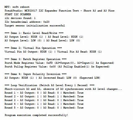
It can be seen that the function test is correct.
IV. Drivers
mcp23017_driver-1.0.1.zip 18 KB
5. BOM & Recommended Alternative Parts
None.
6. Revision History
Document Version | Date of Revision | Modifier | Modified Content |
v1.0 | 2026-03-27 | Ling Gaoxing | Initialize the document |
v1.0.1 | 2026-04-14 | Ling Gaoxing | Modified main.py |
v1.0.2 | 2026-04-21 | Li Zisheng | The production documents have not been exported yet, while all the others have been sorted out completely. |
v1.1 | 2026-04-23 | Xin Ruili | Create an open version of the document, based on the internal document version v1.0.2. |
VII. Relevant Materials
7.1 Chip Datasheet
MCP23017.pdf 995 KB
7.2 Unique Icons for PCB Silk Screen