Contents
- I. Module Introduction
- II. Introduction to Main Chips
- 2.1 Chip Overview
- 2.2 Pin Definition
- 2.3 Functional Block Diagram
- 2.4 Performance Parameters
- 2.5 Reference Circuit
- 2.6 Chip Configuration
- 2.7 Communication Interfaces and Related Protocols
- 2.8 PCB Routing Notes
- III. Circuit Engineering
- 3.1 Circuit Source Engineering
- 3.2 Module Usage Instructions
- 3.3 Application Experiment
- IV. Drivers
- 5. BOM & Recommended Alternative Parts
- 6. Revision History
- VII. Relevant Materials
- 7.1 Chip Datasheet
- 7.2 Unique Icons for PCB Silk Screen
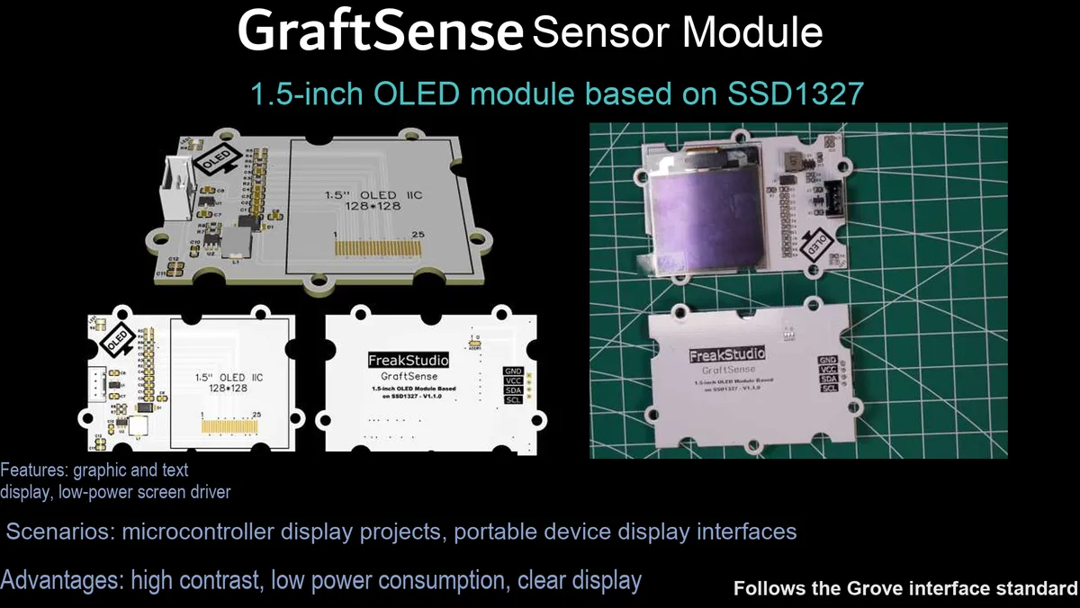
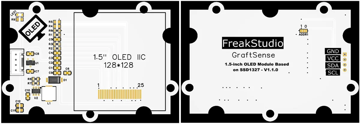
I. Module Introduction
Based on SSD1327 1.5-inch OLED module, using SSD1327 driver chip scheme, equipped with 128 × 128 dot matrix monochrome OLED screen, supporting 16-level phased rollout display and 2000:1 high contrast, rich visual hierarchy, supporting standard I ² C communication interface, can select 0x78 / 0x7A two slave addresses through short circuit, built-in 5V to 3.3V LDO and OLED screen dedicated 15V boost dual power supply circuit, equipped with power filter and indicator circuit Compatible with 3.3V/5V levels, it is suitable for embedded development, maker projects, small instruments and other scenarios that require delicate graphics and text display, providing high-definition and low-power visual interaction capabilities for the system.
II. Introduction to Main Chips
SSD1327 is an I²C / SPI /parallel interface compatible OLED driver chip that supports 128×128 dot matrix monochrome display, integrates built-in 16-level phased rollout control and DC-DC boost circuit, operates at a supply voltage of 3.0V~5.5V, and is capable of driving passive matrix OLED panels. With its high contrast ratio and exquisite grayscale performance, it is widely used in small portable display devices.
2.1 Chip Overview
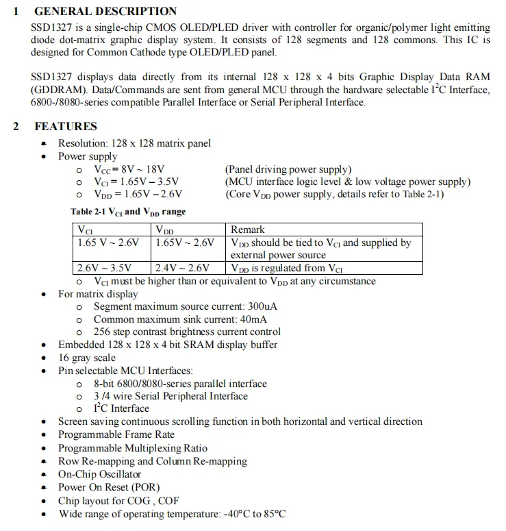
SSD1327 is a single-chip CMOS OLED / PLED driver chip that supports 128×128 dot matrix and 16-level phased rollout display, with a built-in 128×128×4bit graphics display RAM. It can communicate with I²C / SPI / parallel and other multiple interfaces with MCU, features 8V~18V panel driving power supply and 1.65V~3.5V logic power supply, supports functions such as screen scrolling, programmable frame rate and power-on reset, and has an operating temperature range of -40℃~85℃.
2.2 Pin Definition
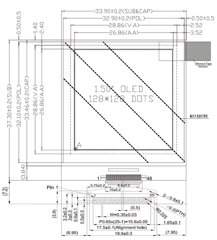
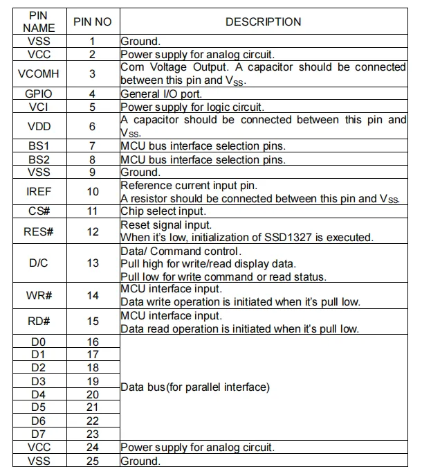
Mechanical dimensions and pin definitions of the 1.5-inch SSD1327 -based OLED module: The screen features a 128×128 dot matrix, with a panel size of approximately 37.3×33.9mm and an active display area of 26.86×26.86mm; pins are categorized into power supply, interface, driving and other types, the communication interface can be configured via BS1 / BS2, and it includes functional pins such as reset, chip select and data/command control, providing the module with flexible hardware connection and configuration capabilities.
2.3 Functional Block Diagram
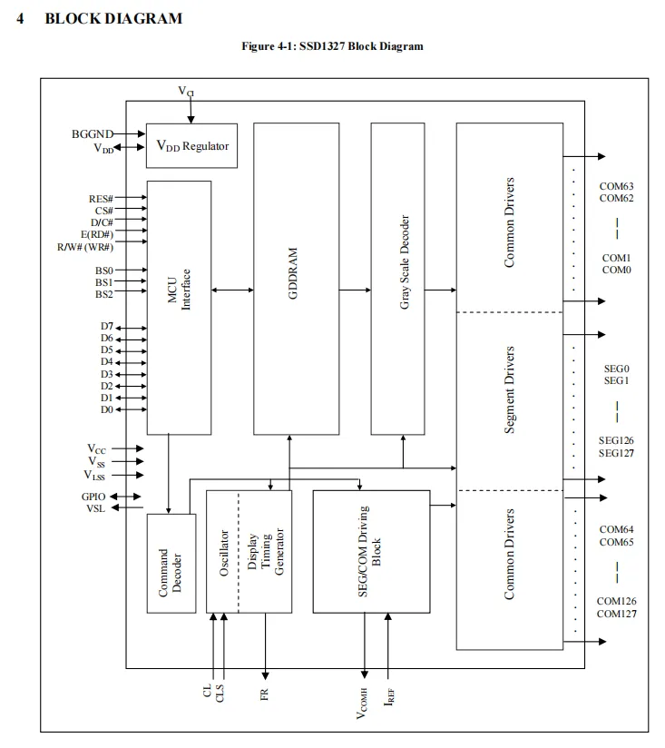
SSD1327 works as follows: it receives commands and data through the MCU interface, stores the display data in the 128×128×4bit GDDRAM, converts them into 16-level grayscale signals via the grayscale decoder, and then outputs driving current to the OLED panel through the segment/common electrode driving circuit. Meanwhile, with built-in power regulator, oscillator and command decoder, it cooperates with the timing generation module to control display refresh, realizing high-contrast, low-power phased rollout visual output.
2.4 Performance Parameters
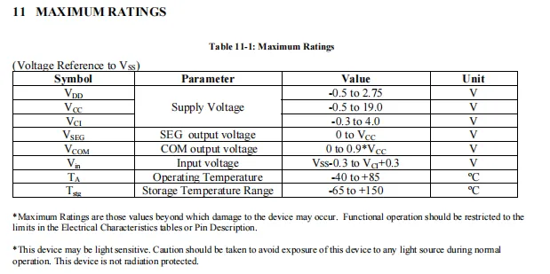
SSD1327 absolute maximum ratings table specifies that the core power supply VDD ranges from -0.5V to 2.75V, the panel driver power supply VCC ranges from -0.5V to 19V, the logic interface power supply VCI ranges from -0.3V to 4V, the operating temperature ranges from -40°C to 85°C, and the storage temperature ranges from -65°C to 150°C. Exceeding these ranges will cause permanent damage to the device, which is also sensitive to light and shall be protected from light exposure during normal operation.
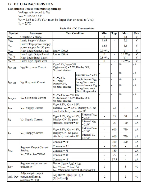
SSD1327 DC electrical characteristics table, under the recommended operating conditions of VDD = 1.65V∼2.6V, VCC = 8V∼18V, VCI = 1.65V∼3.5V, is compatible with 3.3V logic levels, features extremely low operating current (typical IDD of 22μA, typical ICC of 600μA), a sleep mode current of only 1~10μA, and 16-level phased rollout current control with uniform display performance, making it suitable for low-power compact OLED display devices.
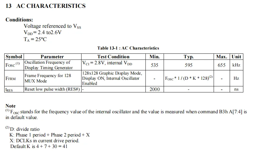
SSD1327 AC electrical characteristic table shows that under the condition of VDD = 2.4V ~ 2.6V, the oscillation frequency of the built-in display timing generator is 535~655kHz (typical 595kHz), which can generate a programmable frame rate; the low-level pulse width of the reset pin RES shall be at least 2000ns to complete the chip initialization.
2.5 Reference Circuit
None.
2.6 Chip Configuration
None.
2.7 Communication Interfaces and Related Protocols
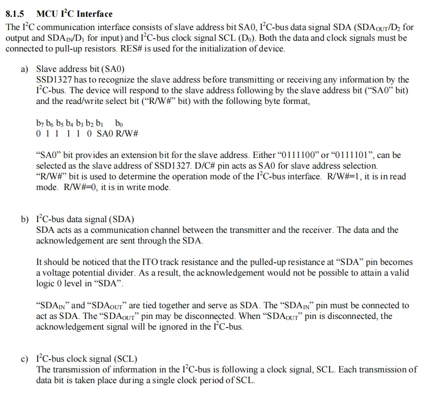
SSD1327 I²C interface specification: only slave mode is supported. D0 / D1 serve as SCL / SDA respectively (pull-up resistors connected to the same potential as VCI are required). The D/C# pin configures SA0 to select between the two slave addresses 0x78 / 0x7A. Following the communication format of " START + slave address + R/W# bit + data/command + ACK ", it achieves reliable phased rollout OLED display control.
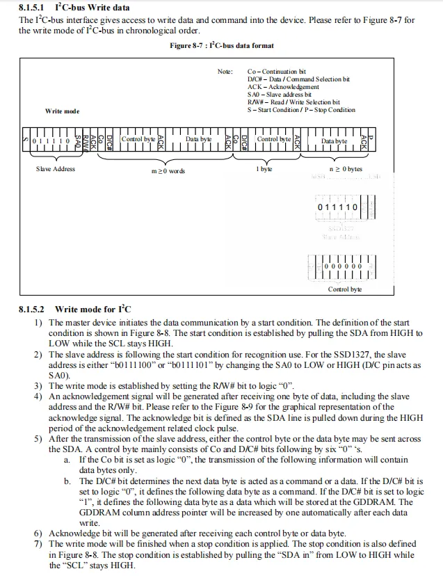
SSD1327 's I²C write operation protocol: The master initiates communication with a START condition, sends the slave address (0x78 / 0x7A) containing the SA0 bit, sets R/W# to 0 to enter write mode, and an ACK response follows each byte; by controlling the Co bit and D/C# bit of the control byte, commands or display data can be transmitted continuously, and the transmission is finally terminated with a STOP condition to realize the phased rollout display control of the OLED screen.
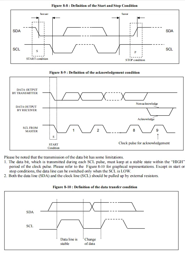
SSD1327 's I ² C timing specification: When SCL is high, SDA changes from high to low as a START start condition, and from low to high as a STOP end condition. When SCL is high, SDA data must remain stable, only allowing SDA level changes when SCL is low; after each byte, the receiver pulls down the SDA to generate an ACK response, and SDA and SCL need to be externally pulled up by a resistor to ensure reliable communication.
2.8 PCB Routing Notes
None.
III. Circuit Engineering
3.1 Circuit Source Engineering
To obtain the circuit source project, please follow the official account [Freak Embedded].
3.2 Module Usage Instructions
The schematic diagram of this module is shown below:
SCH_1.5-inch OLED Module Based on SSD1327-V1.0.0_2026-03-31.pdf 2.3 MB
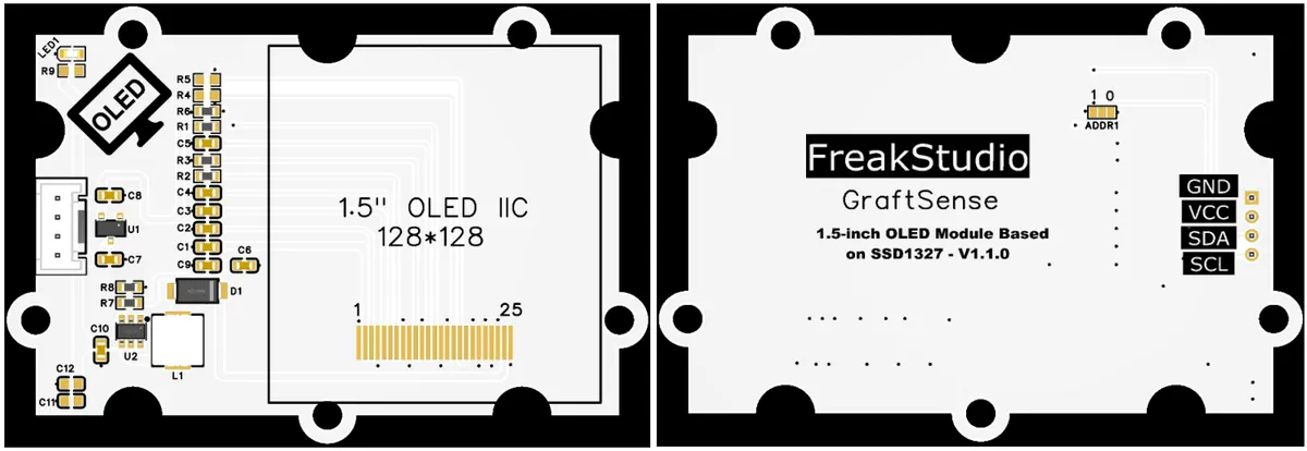
This module provides a IIC communication interface: it supports standard I²C communication baud rates, and allows selection between the two slave addresses ADDR1 via the short-circuit jumper: 0x78 / 0x7A. It features a built-in dual power supply circuit consisting of a 5V-to-3.3V LDO and a dedicated 15V boost converter for OLED panels, along with power filtering and indicator circuits. Compatible with both 3.3V and 5V logic levels, it can stably drive a 128×128 dot-matrix, 16-level phased rollout OLED screen, delivering exquisite and rich visual performance with a high contrast ratio of 2000:1. Suitable for scenarios requiring clear graphics and text display such as embedded development, maker projects, and compact instruments, this module equips systems with low-power, high-definition visual interaction capabilities.
3.3 Application Experiment
Here, we use the GraftPort-RP2040 development board for testing, and the 1.5-inch OLED module based on SSD1327 communicates with the main controller via the I2C interface.
Here, we first use the HY2.0-4P cable to connect the module to the GraftPort-RP2040 development board's I2C0 interface:
The module connections are shown in the following table:
Development Board Pins | Module Pins | Description |
Pin 4 |
|
|
Pin 5 |
|
|
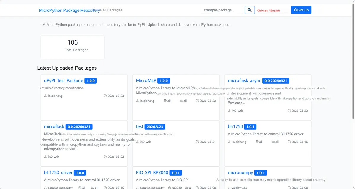
Here, we need to search for the relevant driver packages on uPyPI: https://upypi.net/zh/
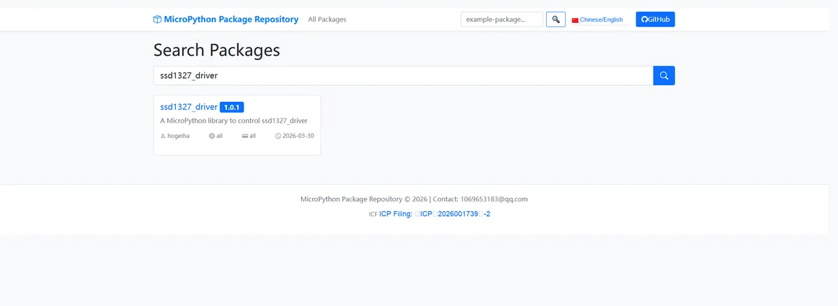
Enter ssd1327_driver to search, and the following will be displayed:
Click to copy the local installation command:
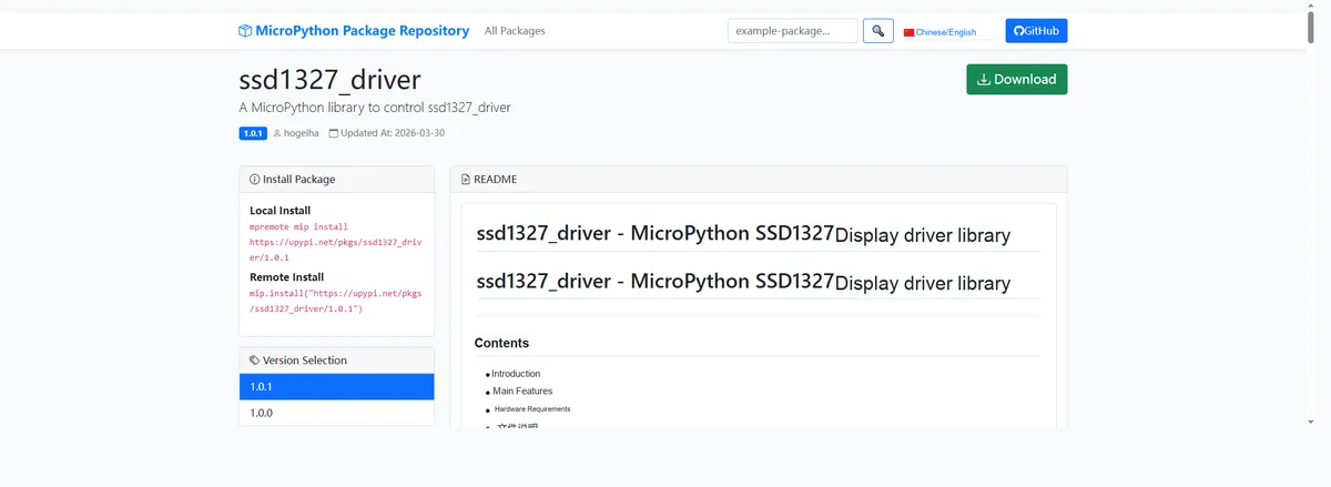
Import the module driver library code via the mip tool. Below are the usage commands for the mpremote tool:
mpremote mip install https://upypi.net/pkgs/ssd1327_driver/1.0.0Import the 1.5-inch OLED module based on SSD1327 - MicroPython driver code, then copy the following main.py code into our project:
# Python env   : MicroPython v1.23.0
# -*- coding: utf-8 -*-
# @Time    : 2026/3/12 5:20 PM
# @Author  : hogeiha
# @File    : main.py
# @Description : Complete SSD1327 OLED display demo, adapted for RP2040/Pico, including text, graphics, contrast, inversion, rotation, scrolling, power on/off, and other functions

# ======================================== Import Modules =========================================

from machine import SoftI2C, Pin
import time
from ssd1327 import WS_OLED_128X128, SEEED_OLED_96X96

# ======================================== Global Variables ============================================

# Automatically identify the sensor address, define a global target address list (supports multiple addresses; use [] even for a single one)
TARGET_OLED_ADDRS = [0x3C ,0x3D]

# ======================================== Functions ============================================

# ======================================== Custom Classes ============================================

# ======================================== Initialization configuration ===========================================

time.sleep(3)
print("FreakStudio: SSD1327 OLED complete demo for RP2040/Pico")

# I2C initialization (compatible with I2C/SoftI2C)
i2c_bus = SoftI2C(sda=Pin(4), scl=Pin(5), freq=100000)

# Start scanning for devices on the I2C bus
devices_list: list[int] = i2c_bus.scan()
print("START I2C SCANNER")

# Check the I2C device scan result
if len(devices_list) == 0:
    print("No i2c device !")
    raise SystemExit("I2C scan found no devices, program exited")
else:
    print("i2c devices found:", len(devices_list))

# Iterate over the address list to initialize the target sensor
sensor = None  # Placeholder for the sensor object initialization
for device in devices_list:
    if device in TARGET_OLED_ADDRS:
        print("I2c hexadecimal address:", hex(device))
        try:
            # Automatically identify and initialize the corresponding sensor
            sensor = WS_OLED_128X128(i2c=i2c_bus, addr=device)
            print("Sensor initialization successful")
            break
        except Exception as e:
            print(f"Sensor Initialization failed: {e}")
            continue
else:
    # Target device not found, raise an exception
    raise Exception("No target sensor device found in I2C bus")

# ========================================  Main Program  ============================================

# ---------------------- 1. Clear screen demo ----------------------
# Fill the entire screen with grayscale value 0 (all black) to clear the screen
sensor.fill(0)
# Refresh the display memory contents to the OLED screen
sensor.show()
# Print the screen-clear-complete message, wait 0.5 seconds
print("Screen cleared, waiting for 0.5 seconds...")
time.sleep(0.5)

# ---------------------- 2. Display text (supports different grayscale levels) ----------------------
# Clear the screen, prepare to show text
sensor.fill(0)
# Display text at coordinates (8,8), grayscale value 15 (brightest)
sensor.text("SSD1327 Demo", 8, 8, 15)
# Display the screen resolution text at coordinates (8,20), grayscale value 10 (medium brightness)
sensor.text(f"{sensor.width}x{sensor.height} OLED", 8, 20, 10)
# Display the device information text at coordinates (8,32), grayscale value 5 (low brightness)
sensor.text("MicroPython Pico", 8, 32, 5)
# Display the grayscale mode text at coordinates (8,44), grayscale value 2 (very dim)
sensor.text("GS4 Grayscale", 8, 44, 2)
# Refresh the screen to show the text content
sensor.show()
# Print the text-display-complete message, wait 2 seconds
print("Text display completed, waiting for 2 seconds...")
time.sleep(2)

# ---------------------- 3. Draw graphics: pixels + lines ----------------------
# Clear the screen, prepare to draw graphics
sensor.fill(0)
# Loop to draw gradient pixels, x coordinate step 8
for x in range(0, sensor.width, 8):
    # Calculate the gradient grayscale value from the x coordinate (range 0-15)
    gray = x // (sensor.width // 16)
    # Loop to draw gradient pixels, y coordinate step 8
    for y in range(0, sensor.height, 8):
        # Draw a pixel with the specified grayscale value at coordinates (x,y)
        sensor.pixel(x, y, gray)

# Draw the main diagonal line, start (0,0), end (screen width-1,screen height-1), grayscale value 15 (brightest)

sensor.line(0, 0, sensor.width - 1, sensor.height - 1, 15)
# Draw the anti-diagonal line, start (0,screen height-1), end (screen width-1,0), grayscale value 10 (medium brightness)
sensor.line(0, sensor.height - 1, sensor.width - 1, 0, 10)
# Display text at the vertical middle of the screen, grayscale value 15 (brightest)
sensor.text("Pixels & Lines", 8, sensor.height // 2, 15)
# Refresh the screen to show the graphics and text
sensor.show()
# Print the graphics-drawing-complete message, wait 2 seconds
print("Pixels and lines drawing completed, waiting for 2 seconds...")
time.sleep(2)

# Addition: draw rectangles (hollow/filled)
# Clear the screen, prepare to show the rectangle-related text
sensor.fill(0)
# Display the rectangle prompt text at the vertical middle of the screen, grayscale value 15 (brightest)
sensor.text("Rectangles", 8, sensor.height // 2, 15)
# Refresh the screen to show the text
sensor.show()
# Print the rectangle-drawing-complete message, wait 2 seconds
print("Rectangles drawing completed, waiting for 2 seconds...")
time.sleep(2)

# ---------------------- 4. Adjust contrast (0-255, default 0x7f=127) ----------------------
# Clear the screen, prepare to show the contrast prompt text
sensor.fill(0)
# Display the maximum contrast prompt text at coordinates (8,8), grayscale value 15 (brightest)
sensor.text("Contrast: 255", 8, 8, 15)
# Refresh the screen to show the text
sensor.show()
# Set the OLED screen contrast to 255 (maximum)
sensor.contrast(255)
# Print the maximum-contrast-set message, wait 1 second
print("Set maximum contrast, waiting for 1 second...")
time.sleep(1)

# Clear the screen, prepare to show the low contrast prompt text
sensor.fill(0)
# Display the low contrast prompt text at coordinates (8,8), grayscale value 15 (brightest)
sensor.text("Contrast: 32", 8, 8, 15)
# Refresh the screen to show the text
sensor.show()
# Set the OLED screen contrast to 32 (low value)
sensor.contrast(32)
# Print the low-contrast-set message, wait 1 second
print("Set low contrast, waiting for 1 second...")
time.sleep(1)

# Restore the OLED screen default contrast (127)
sensor.contrast(0x7F)
# Print the default-contrast-restored message
print("Restore default contrast")

# ---------------------- 5. Invert display (black/white or grayscale inversion) ----------------------
# Clear the screen, prepare to show the normal display mode prompt text
sensor.fill(0)
# Display the normal display mode text at coordinates (8,8), grayscale value 15 (brightest)
sensor.text("Normal Display", 8, 8, 15)
# Refresh the screen to show the text
sensor.show()
# Print the normal-display-mode message, wait 1 second
print("Normal display mode, waiting for 1 second...")
time.sleep(1)

# Turn on the OLED display inversion (grayscale values inverted)
sensor.invert(1)
# Display the inverted mode text at coordinates (8,20), grayscale value 15 (brightest)
sensor.text("Inverted", 8, 20, 15)
# Refresh the screen to show the text
sensor.show()
# Print the inverted-display-mode message, wait 1 second
print("Inverted display mode, waiting for 1 second...")
time.sleep(1)

# Turn off the OLED display inversion, restore normal display
sensor.invert(0)
# Print the normal-display-restored message
print("Restore normal display")

# ---------------------- 6. Rotate display (180 degrees) ----------------------
# Clear the screen, prepare to show the original orientation prompt text
sensor.fill(0)
# Display the original orientation text at coordinates (8,8), grayscale value 15 (brightest)
sensor.text("Original", 8, 8, 15)
# Refresh the screen to show the text
sensor.show()
# Print the original-display-orientation message, wait 1 second
print("Original display direction, waiting for 1 second...")
time.sleep(1)

# Set the OLED screen to 180-degree rotated display
sensor.rotate(True)
# Display the rotation prompt text at coordinates (8,20), grayscale value 15 (brightest)
sensor.text("Rotated 180 degrees", 8, 20, 15)
# Refresh the screen to show the text
sensor.show()
# Print the 180-degree-rotation message, wait 1 second
print("180 degrees rotated display, waiting for 1 second...")
time.sleep(1)

# Restore the OLED screen original display orientation
sensor.rotate(False)
# Print the original-display-orientation-restored message
print("Restore original display direction")

# ---------------------- 7. Software scrolling ----------------------
# Clear the screen, prepare to show the scroll demo prompt text
sensor.fill(0)
# Display the scroll demo text at the vertical middle of the screen, grayscale value 15 (brightest)
sensor.text("Scroll Demo", 8, sensor.height // 2, 15)
# Refresh the screen to show the text
sensor.show()
# Print the scroll-demo-start message, wait 1 second
print("Scroll demo started, waiting for 1 second...")
time.sleep(1)

# Scroll-down demo: loop 32 times, scrolling down 1 pixel each time
for i in range(0, 32):
    # Set the screen scroll offset, 0 pixels horizontal, 1 pixel vertical (downward)
    sensor.scroll(0, 1)
    # Refresh the screen to show the scrolling effect
    sensor.show()
    # Scroll at an interval of 0.05 seconds each time
    time.sleep(0.05)

# Scroll-up demo: loop 32 times, scrolling up 1 pixel each time
for i in range(0, 32):
    # Set the screen scroll offset: 0 pixels horizontally, -1 pixel vertically (up)
    sensor.scroll(0, -1)
    # Refresh the screen to show the scrolling effect
    sensor.show()
    # Scroll at an interval of 0.05 seconds each time
    time.sleep(0.05)
# Print the scroll demo completion message
print("Scroll demo completed")

# ---------------------- 8. Power off/on demo ----------------------
# Clear the screen, ready to show the power-off message text
sensor.fill(0)
# Show the power-off message text at the vertical middle of the screen, grayscale value 15 (brightest)
sensor.text("Power Off...", 8, sensor.height // 2, 15)
# Refresh the screen to show the text
sensor.show()
# Print the about-to-power-off message, wait 1 second
print("About to turn off the screen, waiting for 1 second...")
time.sleep(1)

# Turn off the OLED screen (low-power mode, display memory content retained)
sensor.poweroff()
# Print the screen-off message, wait 2 seconds
print("Screen turned off, waiting for 2 seconds...")
time.sleep(2)

# Turn on the OLED screen (display resumes, display memory content retained)
sensor.poweron()
# Clear the screen, ready to show the power-on message text
sensor.fill(0)
# Show the power-on message text at the vertical middle of the screen, grayscale value 15 (brightest)
sensor.text("Power On!", 8, sensor.height // 2, 15)
# Refresh the screen to show the text
sensor.show()
# Print the screen-on message, wait 2 seconds
print("Screen turned on, waiting for 2 seconds...")
time.sleep(2)

# ---------------------- Final screen clear ----------------------
# Fill the entire screen with grayscale value 0 (all black) to do the final screen clear
sensor.fill(0)
# Refresh the screen to complete the clear
sensor.show()
# Print the demo completion message
print("Demo completed, screen cleared")
Burn the code, open the terminal, and the output is as follows:
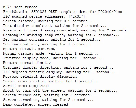
The demo content is as follows:
- Clear Screen Demo
- Display text (supporting different phased rollout schemes)
- Drawing Graphics: Pixels + Lines
- Adjust contrast (0-255, default 0x7f = 127)
- Inverted Display (Black/White / phased rollout Inversion)
- Rotate Display (180 Degrees)
IV. Drivers
ssd1327_driver-1.0.1.zip 16 KB
5. BOM & Recommended Alternative Parts
None.
6. Revision History
Document Version | Date of Revision | Modifier | Modified Content |
v1.0 | 2026-03-27 | Ling Gaoxing | Initialize the document |
v1.0.1 | 2026-04-21 | Li Zisheng | The production documents have not been exported yet, while all the others have been sorted out completely. |
v1.1 | 2026-04-23 | Xin Ruili | Create an open version of the document, based on the internal document version v1.0.1. |
VII. Relevant Materials
7.1 Chip Datasheet
SSD1327-datasheet.pdf 986 KB
7.2 Unique Icons for PCB Silk Screen