
Contents
- 1. Module Introduction
- 2. Usage of Basic Building Blocks
- 2.1 Initialization Block (Init MPU6050 IMU: I2C. .., SCL. .., SDA. ..)
- 2.2 Gyroscope X-axis Reading Block (Gyro - X axis)
- 2.3 Gyroscope Y-axis Reading Block (Gyro - Y axis)
- 2.4 Gyroscope Z-axis Reading Block (Gyro - Z axis)
- 2.5 Acceleration X-axis Reading Block (Acceleration - X axis)
- 2.6 Acceleration Y-axis Read Block (Acceleration - Y axis)
- 2.7 Acceleration Z-axis Reading Block (Acceleration - Z axis)
- 3. Wiring Instructions
- 4. Install the MPU6050 library function
- 5. Example: Read acceleration data and print it
Young makers, today let’s unlock a "black-tech module that can detect posture" 🎮!
When you play motion-sensing games, the controller moves the in-game character in sync with your actions; self-balancing scooters stay upright without tipping over; smartphones automatically switch between portrait and landscape modes. .. Behind all these functions lies a type of sensor capable of detecting "motion posture". Today, we are going to get to know the six-axis gyroscope module based on the MPU6050 ✨, which can inform the development board of: 👉 whether I am tilting forward or backward, or turning left or right?
1. Module Introduction
Want to make your development board "sense its own movements" just like a human? This six-axis module is the core component you need!
It is a inertial measurement unit (IMU) with a built-in "3-axis accelerometer" and "3-axis gyroscope":
- 📊 Triaxial accelerometer: It detects the acceleration of the module in the three directions of X, Y and Z (such as the force exerted when pushing forward or lifting upward), and can determine "whether there is movement and in which direction the movement is going".
- 🎡 3-axis gyroscope: Detects the angular velocity of the module in the three X, Y, Z directions (such as the speed of turning left or right), and can determine "whether it is rotating and in which direction it is rotating".
When combined, the two enable the development board to accurately perceive its own motion attitude, providing richer information than a single sensor.
Compared with ordinary sensors, it has the following characteristics:
- 🎯 Six-axis integration: Detects acceleration and rotation simultaneously, acquiring 6 sets of data in one go;
- 🚀 Responsive: Capable of capturing subtle motion changes, making it ideal for somatosensory control;
- 🧩 Wide range of applications: It can be used in everything from motion-sensing games to self-balancing scooters.
In graphical programming, these blocks are commonly used for six-axis gyroscopes:
Init MPU6050 IMUBlock: Initialize the sensor and configure the I2C communication pins;Acceleration - X/Y/Z axisBlock: Read acceleration values in three directions;- Forever block: continuously detect posture changes;
printBlock: Print six-axis data to the terminal;- Delay block: Controls the detection frequency.
In practical projects, it is often used for the following purposes:
- Somatosensory control device (e. g., controlling the on/off of LEDs via hand gestures)
- Attitude detection of the balancing vehicle (to keep the vehicle from tipping over)
- Motion sensing of interactive toys (e. g., sound effects triggered by shaking)
Quick Science: Accelerometer vs. Gyroscope
- Accelerometer: It acts like a "motion intensity detector" that can tell you "whether you are accelerating right now and in which direction". For example, if you lift the module upward, the acceleration on the Z-axis will increase.
- Gyroscope: It acts like a "rotation speed detector" that can tell you "whether you are rotating right now and how fast you are rotating". For example, if you turn the module to the left, the value of the X-axis gyroscope will change.
2. Usage of Basic Building Blocks
2.1 Initialization Block (Init MPU6050 IMU: I2C. .., SCL. .., SDA. ..)
This block acts as the "power-on key" for the MPU6050 six-axis gyroscope; without it, the subsequent 6 reading blocks will be completely useless!
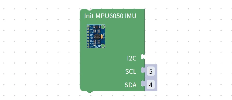
First, figure this out: Why do we need initialization?
MPU6050 is a six-axis sensor based on I2C communication (integrating a 3-axis accelerometer and a 3-axis gyroscope), which needs to establish a dedicated communication link with the I2C bus and designated pins of the development board — different development boards are equipped with multiple I2C buses (such as I2C0 and I2C1), and the SCL/SDA pins can also be connected to different GPIO pins.
The function of this building block is to convey three key pieces of information to the development board: "Which I2C bus am I using? ", "Which pin is the SCL connected to? ", and "Which pin is the SDA connected to? ", so as to enable a successful "handshake" between the development board and the MPU6050.
Chinese meaning: Initialize the (Init) MPU6050 six-axis inertial measurement unit (IMU), select the I2C bus (I2C) to be used, and specify the connected SCL pin (SCL) and SDA pin (SDA).
When the program runs to this block, the development board will send an I2C initialization command to establish a communication connection with the MPU6050. After the handshake succeeds, the sensor enters the "standby state" and starts continuously collecting accelerometer and gyroscope data; if you skip initialization and directly use the subsequent reading block, the program will report an error and fail to read any data at all — just like trying to enter your house without entering the password, the door won't open at all!
Tips
- Do not reverse the pins! The SCL and SDA pins selected during initialization must be exactly the same as the pins actually connected. For example, if SCL is actually connected to Pin5 and SDA to Pin4, do not select the reverse in the blocks, otherwise the sensor will "play dead" and not respond;
- Don’t make the wrong choice of I2C bus! Most development boards come with two buses, I2C0 and I2C1, and selecting the wrong one will result in communication failure; beginners are recommended to prioritize I2C0.
- Initialization only needs to be performed once! Just place this block at the very beginning of the program; there is no need to repeatedly initialize it inside a loop, otherwise it will waste the resources of the development board and may even cause data disorder.
✨ Interactive Quick Question
Think about it: What will happen if you skip the initialization block and directly use the "Acceleration - X axis" read block? (Answer: The program cannot recognize the MPU6050 sensor, and will read invalid data (such as 0) or report an error directly!)
2.2 Gyroscope X-axis Reading Block (Gyro - X axis)
This block is a tool for detecting the "X-axis rotation speed" of the development board, and its task is to read the X-axis gyroscope data of the MPU6050.
First, figure out: What is this data used for?
A gyroscope can detect the angular velocity of rotation of the development board (unit: °/s, i. e., the angle rotated per second). For example, when the development board flips left around the X-axis, the reading of the X-axis gyroscope will be a positive value; when it flips right, the reading will be a negative value.
Chinese meaning: Read the angular velocity value of the X-axis gyroscope of the (Gyro) MPU6050 sensor.
When the program runs to this block, it will retrieve the X-axis gyroscope data from the MPU6050 buffer and return a specific number (e. g., 10, -20,5): the sign of the value indicates the rotation direction, and the absolute value indicates the rotation speed (the larger the value, the faster the rotation). This number can be used to detect the flipping action of the development board (such as "left/right turn" in somatosensory games).
Tips
- Static reference value! When the development board is stationary, the gyroscope reading is approximately 0°/s (there will be slight drift, which can be eliminated through calibration);
- Reference for the value range! The default range commonly used by beginners is (-250°/s ~ + 250°/s); for example, the value will approach ±250 when flipping quickly.
✨ Interactive Quick Question
Think about it: If you quickly flip the development board to the left around the X-axis, will the value of the X-axis gyroscope become a positive number or a negative number? (Answer: Positive! When flipping to the left, the rotational angular velocity along the X-axis is positive~)
2.3 Gyroscope Y-axis Reading Block (Gyro - Y axis)
This block is a "close sibling" of the X-axis gyroscope reading block, and its task is to read the Y-axis gyroscope data of the MPU6050.

First, figure out: what's the use of this data?
The Y-axis gyroscope can detect the rotational angular velocity of the development board in the front-back direction. For example, when the development board flips forward around the Y-axis, the value of the Y-axis gyroscope will become a positive number; when it flips backward, the value will become a negative number.
Chinese meaning: Read the angular velocity value of the Y-axis gyroscope of the (Gyro) MPU6050 sensor.
When the program runs to this block, it will retrieve the Y-axis gyroscope data from the MPU6050 buffer and return a specific number (e. g., 15, -12,8). This value can be used to detect the forward/backward flipping motion of the development board, such as the "look down / look up" action in somatosensory games.
Tips
- Combine the acceleration data! The combination of gyroscope and acceleration data can more accurately determine the attitude of the development board (such as the "complementary filtering" algorithm);
- Watch out for drift! The gyroscope will have slight drift when stationary, and it needs calibration after prolonged use.
✨ Interactive Quick Question
Quick Quiz: When you flip the development board quickly forward around the Y-axis, will the value of the Y-axis gyroscope increase or decrease? (Answer: It increases! When flipping forward, the rotational angular velocity along the Y-axis is positive, so the value will rise from 0 to tens or even hundreds~)
2.4 Gyroscope Z-axis Reading Block (Gyro - Z axis)
This block is a core tool for detecting the "Z-axis rotation speed" of the development board, and its task is to read the Z-axis gyroscope data of the MPU6050.

First, figure out: What is this data used for?
The Z-axis gyroscope can detect the horizontal rotation angular velocity of the development board (such as "turn left / turn right"). For example, when the development board rotates left around the Z-axis, the value of the Z-axis gyroscope will become a positive number; when it rotates right, the value will become a negative number.
Chinese meaning: Read the Z-axis gyroscope angular velocity value of the (Gyro) MPU6050 sensor.
When the program runs to this block, it will retrieve the Z-axis gyroscope data from the MPU6050 buffer and return a specific number (e. g., 20, -18,10). This value can be used to detect horizontal rotation movements of the development board, such as the "steering control" of a somatosensory car.
Tips
- Static Reference Value! When the development board is stationary, the Z-axis gyroscope reading is approximately 0°/s;
- Shake Detection! When you shake the development board rapidly, the value of the Z-axis gyroscope will change drastically, which can be used as the judgment basis for "somatosensory trigger"(e. g., somatosensory dice rolling).
✨ Interactive Quick Question
Think about it: If you quickly rotate the development board to the right around the Z-axis, will the value of the Z-axis gyroscope become a positive number or a negative number?
Answer: Negative! When rotating clockwise, the angular velocity in the Z-axis direction is negative~
2.5 Acceleration X-axis Reading Block (Acceleration - X axis)
After the sensor is initialized, it's time to use this "Fetch Parcel" block to read out the X-axis acceleration data collected by the MPU6050 for the program to use!

First, figure out: What is this data used for?
The Acceleration Sensor can detect the "force changes" of the development board in the X-axis direction, such as tilting, shaking, and impact, with the unit being g (gravitational acceleration, 1g≈9.8m/s²). For example, when the development board tilts to the left, the X-axis acceleration will become a positive value; when it tilts to the right, the X-axis acceleration will become a negative value.
Chinese meaning: Read the X-axis acceleration value of the MPU6050 acceleration sensor.
When the program runs to this block, it will retrieve the X-axis acceleration data from the MPU6050 buffer and return a specific number (e. g., 0.2, -0.5, 1.0): the sign of the value indicates the direction, and the absolute value represents the magnitude of the acceleration. This number can be used to detect the tilt angle of the development board and shaking motions (such as the trigger logic for motion-controlled dice rolling).
Tips
- Do NOT reverse the order! If you read the acceleration first and then initialize the sensor, the data you get will be invalid (e. g., 0);
- Numerical range reference! The default range commonly used by beginners is (-2g to + 2g). For example, when the development board is placed flat, the acceleration of the X-axis is approximately 0g, and when it is stood vertically, the acceleration is about 1g;
- Note on anti-jitter: The acceleration data may have slight fluctuations, and you can make the data more stable by "taking multiple readings and calculating the average value".
✨ Interactive Quick Question
Quick Response Quiz: When you tilt the development board to the left, will the acceleration value of the X-axis become positive or negative? (Answer: Positive! When tilted to the left, the acceleration in the X-axis direction is positive~)
2.6 Acceleration Y-axis Read Block (Acceleration - Y axis)
This block is a "close sibling" of the X-axis reading block, and its task is to read the Y-axis acceleration data of the MPU6050.

First, figure out: what's the use of this data?
Y-axis acceleration can detect the tilt or shake of the development board in the front-back direction. For example, when the development board tilts forward, the Y-axis acceleration will become a positive value; when it tilts backward, the Y-axis acceleration will become a negative value.
Chinese meaning: Read the acceleration value of the Y-axis (Acceleration) of the MPU6050 sensor. Y axis
When the program runs to this block, it will retrieve the Y-axis acceleration data from the MPU6050 buffer and return a specific value (e. g., 0.3, -0.4, 0.9). This value can be used to detect the forward and backward tilt angle of the development board, for example, to control forward/backward movement when making a "somatosensory car".
Tips
- Reference value for horizontal placement: When the development board is placed horizontally, the acceleration of the Y-axis is approximately 0g;
- Use it in combination with the X-axis! By reading the accelerations of the X and Y axes simultaneously, you can determine the 2D tilt direction of the development board (such as top-left, bottom-right).
✨ Interactive Quick Question
Think about it: If you tilt the development board forward, will the acceleration value of the Y-axis increase or decrease? (Answer: It increases! When tilted forward, the acceleration in the Y-axis direction is positive, and the value will rise from 0 to around 1g~)
2.7 Acceleration Z-axis Reading Block (Acceleration - Z axis)
This building block is the core tool for detecting the "vertical force bearing" of the development board, and its task is to read the Z-axis acceleration data of the MPU6050.

First, figure out: what's the use of this data?
The Z-axis acceleration can detect the force exerted on the development board in the vertical direction. For example, when the development board is placed horizontally, the Z-axis acceleration is approximately 1g (subject to Earth's gravity); when it is lifted upward, the acceleration will be greater than 1g (due to additional acceleration); when it falls downward, the acceleration will be less than 1g (in a state of weightlessness).
Chinese Meaning: Read the Z-axis acceleration value of the MPU6050 (Acceleration) sensor.
When the program runs to this block, it will retrieve the Z-axis acceleration data from the MPU6050 buffer and return a specific value (e. g., 0.9, 1.2, 0.5). This value can be used to detect vertical movement of the development board (such as "fall detection") or determine whether the board is placed horizontally.
Tips
- Horizontal reference value! When the development board is placed horizontally, the acceleration of the Z-axis is approximately 1g (normal gravity);
- Distinguish between gravity and motion! When stationary, the value on the Z-axis is approximately 1g, and the changes that occur during movement are caused by additional acceleration.
✨ Interactive Quick Question
Quick Response: If you quickly lift the development board upward, will the acceleration value on the Z-axis be greater than 1g or less than 1g?
Answer: It's greater than 1g! When you lift it upward, an additional upward acceleration is generated, and when superimposed with gravity, the value will exceed 1g~
3. Wiring Instructions
To make the module "sense the posture", the first step is still —— connect the wires correctly!
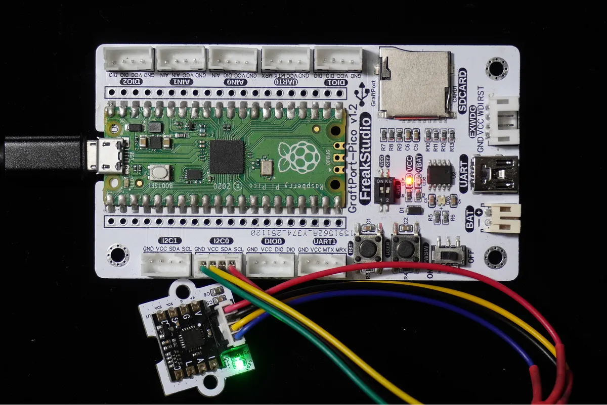
We will connect the MPU6050-based six-axis gyroscope module to the I2C0 interface of the development board, with the corresponding relationship as follows:
Development Board Pins | Module Pins | Description |
Pin 4 |
| I2C data transmission line, corresponding to |
Pin 5 |
| I2C clock signal line, corresponding to |
📌 Note
- The MPU6050 communicates via I2C, and the SCL and SDA pins must be connected correctly; otherwise, data cannot be read.
- The default I2C address of the module is
0x68, no additional configuration is required.
4. Install the MPU6050 library function
Before using graphical building blocks, you need to install two driver libraries first:
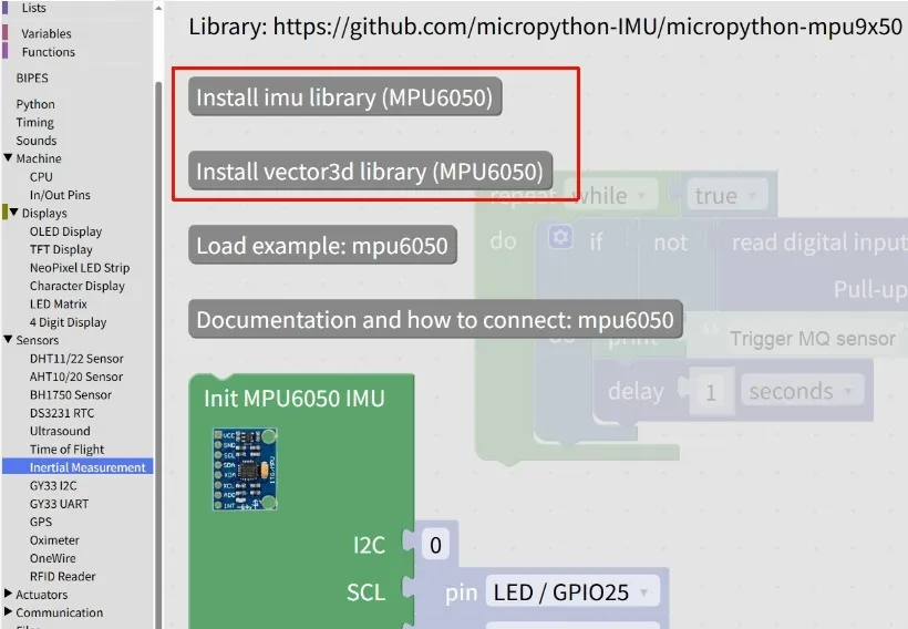
- Locate and click
Install imu library (MPU6050)to install the core driver; - Then click
Install vector3d library (MPU6050)to install the data processing library;
5. Example: Read acceleration data and print it
Test Objective: Continuously detect the acceleration values of the module in the X, Y, and Z directions, print the values to the terminal in real time, and intuitively perceive the correspondence between "action → value change".
Little Life Insight: The "Shake" feature on mobile phones relies on a similar accelerometer to detect your shaking motions, so let's build a "motion sensor" right now!
The graphical program is as follows:
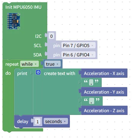
Building Block Assembly Steps:
- Initialize the sensor
- Drag in
the Init MPU6050 IMUblock; - Set
I2Cto0(corresponding to the I2C0 interface); SCLselectsPin 7 / GPIO5,SDAselectsPin 6 / GPIO4, which matches the wiring configuration.
- Drag in
- Infinite Loop Detection
- Drag in the
repeat while trueblock to keep the program running continuously.
- Drag in the
- Read and print acceleration data
- Drag a
printblock into the loop, and select the content from thecreate text withblock; - Add
Acceleration - X axis,Acceleration - Y axis, andAcceleration - Z axisblocks in sequence to assemble them into a line of data;
- Drag a
- Add Delay
- Drag a
delayblock to the end of the loop, and set it to1second → this controls the printing frequency and prevents the terminal from being flooded with messages.
- Drag a
Experimental Effect:
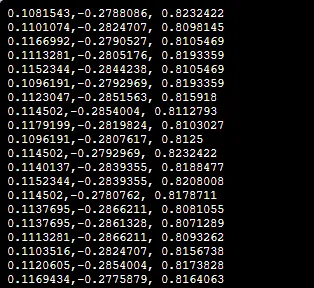
- After the program runs, the terminal will print a set of acceleration values for the X, Y, and Z axes every second (for example,
1.08543 -0.278086 0.823222); - When the module is placed horizontally, the value of the Z-axis is approximately 1 (corresponding to the acceleration due to gravity), while the values of the X-axis and Y-axis are close to 0;
- Tilt the module forward, and the X-axis value will increase; tilt it to the right, and the Y-axis value will increase; lift the module upward, and the Z-axis value will increase.
Graphical blocks will be automatically converted into MicroPython code adapted for the MPU6050, and the running results will be output:
Directly importable building blocks:
IMU.xml 3 KB
Tips
- If data cannot be read:
- Check whether the SCL and SDA pins are connected correctly (Pin7/GPIO5, Pin6/GPIO4) and whether the wiring is secure;
- Confirm that the
imuandvector3dlibraries are installed correctly, then restart the editor and try again; - The module requires a stable power supply to avoid poor contact.
- What should I do if there is an abnormal value?
- When placing the module horizontally, the Z-axis acceleration should be close to 1 (corresponding to the Earth's gravity); if the deviation is too large, you can try recalibrating the module.
- Advanced Gameplay:
- Pair with LED building blocks to realize somatosensory control: tilt forward to turn on the LEDs, and tilt backward to turn off the LEDs;
- Read the gyroscope data, detect the rotation motion of the module, and build a "gesture-controlled car".
✨ Interactive Mini Quiz
- Think: When the module is placed horizontally, why is the value of Z-axis acceleration approximately 1? What is the relationship between this value and the Earth's gravity?
- Try: toss the module quickly upward and catch it again, and see what change will happen to the Z-axis acceleration value? What does this indicate?
Summary
- The six-axis gyroscope module based on MPU6050 is an Inertial Measurement Unit (IMU) that can simultaneously detect three-axis acceleration and three-axis rotation;
- Before use, please complete I2C wiring and dual-library installation as two preparation steps to ensure normal communication;
- It features the advantages of six-axis integration and sensitive response, making it the core component for somatosensory control and attitude detection projects.
- The basic usage is to "read + print" acceleration data, while the advanced usage is to combine it with a gyroscope to achieve more complex attitude control.