
Young makers, earlier we made the LED light up and got the OLED to display content, now it's time to add a "little switch" to the development board — the mechanical pushbutton module! It acts as the "bridge" for interaction between the development board and us: when you press the button, the development board can respond immediately (such as printing a prompt or lighting up an LED), giving you a great sense of "control"~
1. Module Introduction
The mechanical key module is the most fundamental "input gadget", whose core function is to convert our action of "pressing once and releasing once" into an "electrical signal" that the development board can recognize——
- Nature of operation: When the button is not pressed, the internal circuit of the button is disconnected and the pin is at a high level; when the button is pressed, the circuit is closed and the pin becomes a low level. The development board only needs to "read" this level change to know whether you have pressed the button!
- Common uses: controlling the "start/stop" of a program, switching modes (e. g., turning an LED on/off), triggering functions (e. g., displaying new content on an OLED screen), and it is a standard component for all interactive projects.
To master the use of buttons, you mainly need to rely on the cooperation of these types of blocks:
- Set pin mode (input) block: Set the pin connected to the button to "input mode" to be able to read the electrical level;
- Read digital input block: Check the level (high/low) of the key pin to determine whether the key is pressed;
- Conditional (if. .. then. ..) block: performs different actions based on whether the button is pressed or not;
- Delay block (optional): Solves the "key jitter" issue where a single keypress triggers multiple actions;
- External Event (Pin Interrupt) Block: Responds immediately when the button state changes, no need to keep checking in a loop.
With these building blocks, key detection and program logic control can be implemented.
Quick Fact: What exactly is "key switch bounce"?
When a mechanical key is pressed or released, the metal contacts will bounce slightly, causing rapid voltage level transitions (for example, when pressed once, the voltage level goes low → high → low first), which will make the development board mistake it for multiple keystrokes. Adding a short delay (e. g., 200 milliseconds) can "filter" this jitter~
2. Wiring Instructions
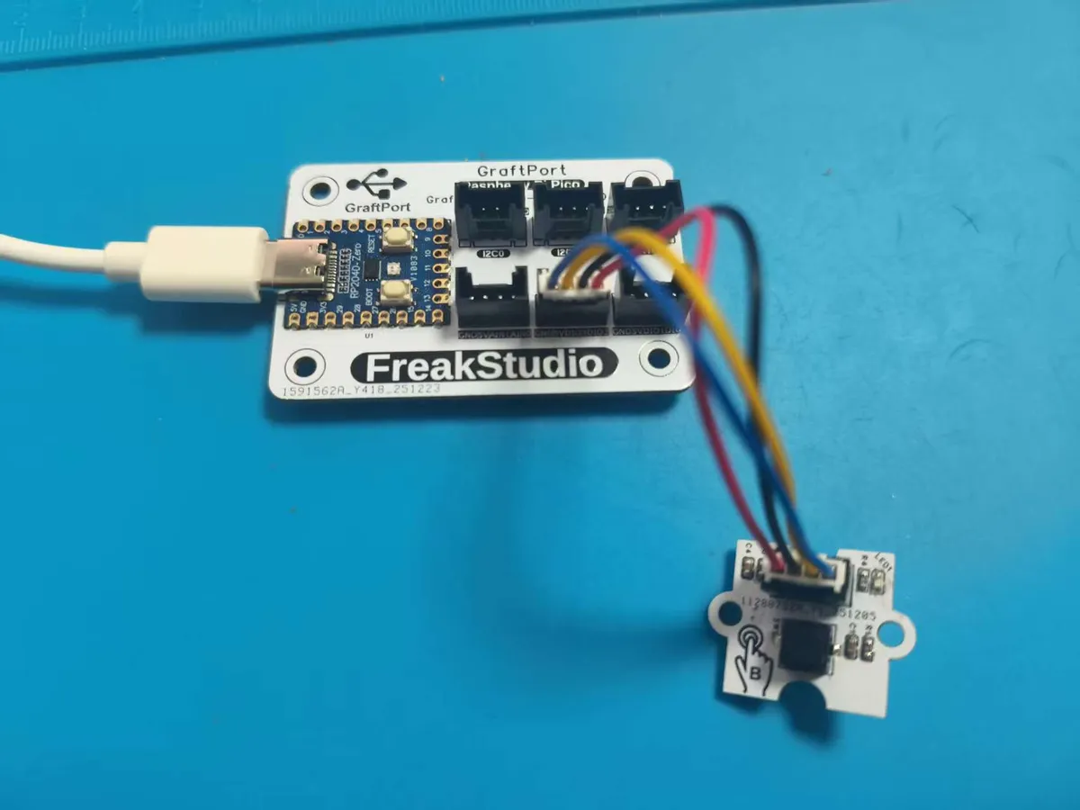
For the development board to recognize a key press, first make sure the wires are connected correctly! We connect the mechanical key module to the DIO1 interface of the development board, and please memorize the specific pin correspondence:
Development Board Pins | Module Pins | Description |
Pin 9 |
| Level signal input pin after key press/release |
Pin 10 |
| - |
3. Example: Key Press Response Example
Experiment Objective: Implement the most basic "key press interaction": the program continuously detects the key status, prints "Key pressed" in the terminal when the key is pressed, stops printing after the key is released, and can also avoid repeated triggering caused by key jitter~
Core Principle: We read the keypad in "pull-up resistor" mode:
- ✅ Key not pressed: GPIO9 pin is high level;
- ✅ Button pressed: GPIO9 pin becomes low level; so by using
not(inversion) to judge the level, you can accurately recognize the "pressed" action!
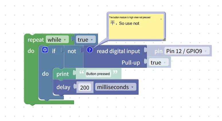
Building Block Assembly Steps (Step-by-Step Guide for You):
- Infinite Loop: Select the
repeat while trueblock → to make the program continuously detect the key status; - Key Press Detection :
- Select
the if not read digital inputblock,set pintoPin 12/GPIO9,set Pull-uptotrue→ detect the level of GPIO9,the notis used to identify the "pressed (low level)" state;
- Select
- Trigger Response:
- Add inside the loop
print "Key pressed"Block → When the key is pressed, the terminal prints a prompt; - Add
delay 200 millisecondsblock → to prevent repeated printing caused by key jitter.
- Add inside the loop
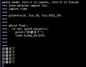
Experimental Effect: After running the program, there is no output in the terminal; when you press the mechanical key, the terminal immediately prints "Key pressed", and stops printing after you release the key. Even if you press/release quickly, there will be no repeated printing~
XML files can be directly imported into the building blocks:
Button module.xml 2 KB
Tips
- If the button doesn't respond when pressed:
- ① Check whether the pin is selected as GPIO9/Pin12;
- ② Check whether Pull-up is set to true (if the pull-up function is not enabled, the level will fluctuate erratically);
- Want more informative prompts? You can change
print "Button pressed"toprint "You pressed the button!", and the development board will follow your instructions obediently~
✨ Interactive Mini Quiz
- Think about it: if you remove
not, the program will behave as "keep printing when no key is pressed, stop printing when a key is pressed". Why? (Answer: When no key is pressed, the pin is at high level 1, sokey_pin.value ()is True, and print will be executed; when a key is pressed, the pin is at low level 0, the condition is not met, so nothing is printed~) - Try it: change the delay to 500 milliseconds, the printing frequency when you press the button will become lower, and feel the impact of jitter yourself~
Summary
- Core logic of the button: After enabling the pull-up resistor, "pressed = low level, not pressed = high level", and using
notto invert the signal can accurately identify the pressing action; - Key to anti-jitter: After a key press is detected, add a delay of 200~500 milliseconds to avoid repeated triggering caused by contact bounce;
- Loop detection is the foundation: Continuously reading the key status via an infinite loop is the easiest-to-understand key detection method. Beginners should master this first before learning the interrupt method~