
Contents
- 1. Pin Selection Block (pin)
- 2. Output Pin Setting Block (set output pin … to …)
- 3. Digital Input Reading Block (read digital input …, pull-up …)
- 4. ADC Input Reading Block (Read RPI Pico ADC Input …)
- 5. PWM Output Configuration Block (PWM#: Pin, Frequency, Duty)
- 6. PWM Frequency Adjustment Block (PWM#… frequency…)
- 7. PWM Duty Cycle Adjustment Block (PWM#… duty…)
- 8. PWM Initialization Block (PWM#… init…)
- 9. PWM Release Block (deinit PWM #)
- 10. Pin Interrupt Block (External event (Interrupt on Input Pin))
Young makers, if the CPU is the "brain" of a development board, then input/output pins (I/O Pins) are the "hands and feet" of the development board!These pins are tiny metal contacts on the development board. Just as our hands can "receive items handed over by others"(input) and "pass things to others"(output), through the pin blocks, programs enable the development board to "read external signals"(such as whether a button is pressed, or the temperature detected by a sensor) and "send commands to the outside"(such as turning on an LED or triggering a buzzer). They are the core of interaction between the development board and external devices!
Whether you want to control a tiny LED, connect a button, a motor or a sensor, you first need to learn to use the pin blocks to "command" these "limbs" to work. Next, we will start with the most basic steps of "selecting a pin" and "controlling output" to unlock the amazing functions of the development board pins~
Tips
The pin numbers vary across different development boards (for example, the onboard LED of some boards is connected to pin 25, while that of others is connected to pin 13). Be sure to check the pinout diagram of your own development board first, and do not select the wrong pin!
✨ Interactive Quick Question
- Think about it: What parts of our body do the "input pins" and "output pins" of a development board resemble respectively? (Answer: Input pins are like ears/eyes (for receiving information), while output pins are like hands/mouth (for sending information)~)
- Quick Quiz: To light up an LED, should we use an input pin or an output pin? (Answer: An output pin! It sends the "turn on" command to the LED~)
1. Pin Selection Block (pin)
Young creators, if you want to command the "hands and feet" of your development board to work, the first step is to tell it "which one to use" — that's exactly what the pin selection block is for! It's just like when we call out "Xiao Ming, come over and help" or "Xiao Hong, give me a hand": specifying "which pin to operate on" in the program is the very first step for all pin-related operations~
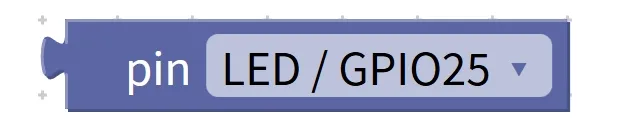
Chinese meaning: Select a specific pin (pin) on the device for subsequent input, output or control operations.
Tips
- Do not select pin numbers arbitrarily! The pins on the development board have fixed numbers (such as 0,1, 25,34, etc.). If you select a non-existent number (such as 100), the program will report an error;
- Different pins serve different functions! Some pins are input-only, while others are output-only. Beginners can start by using the "GPIO pins"(General Purpose Input/Output pins) marked on the development board~
✨ Interactive Quick Question
- Think about it: Can the pin selection block turn on an LED on its own? (Answer: No! It only selects the pin and does not perform any specific operation, so it must be used together with the output setting block~)
- Try this: Find the pin number corresponding to the onboard LED of your development board and write it down — you’ll need it later!
2. Output Pin Setting Block (set output pin … to …)
Once you've selected the right pin, it's time to put this "limb" to work! The output pin setting block is the core tool for the development board to "send commands externally" — it can make a specified pin output either a "high level (1)" or a "low level (0)", just like when we say "turn on the light"(high level) or "turn off the light"(low level), and it can directly control external devices such as LEDs, buzzers, and relays~
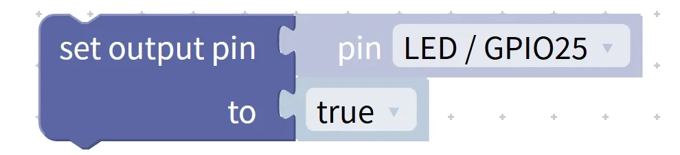
You can think of a pin as a "tiny switch":
- High level (1/true): The switch is turned on, and the pin outputs an electrical signal (powered) to the outside, which can light up the LED and drive the buzzer to sound;
- Low level (0/false): The switch is off, the pin outputs no electrical signal (no power), the LED will turn off, and the buzzer will stop.
The output state of the pin will remain unchanged consistently until you modify it again or the development board restarts.
Chinese meaning: Set ( set ) an output pin ( output pin ) to ( to ) the specified state, such as 1 high level ( true ) or 0 low level ( false ).
Hands-on Practice: Turn on the onboard LED connected to Pin 25
将 输出引脚 25 设置为 高电平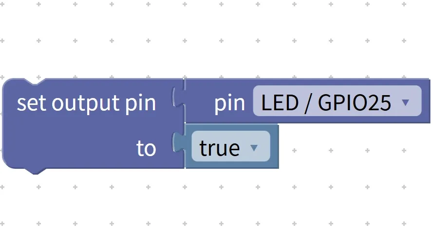
Execution Result: The onboard green LED on the development board lights up immediately, and it will stay on continuously as long as the pin state is not modified and the development board is not restarted~
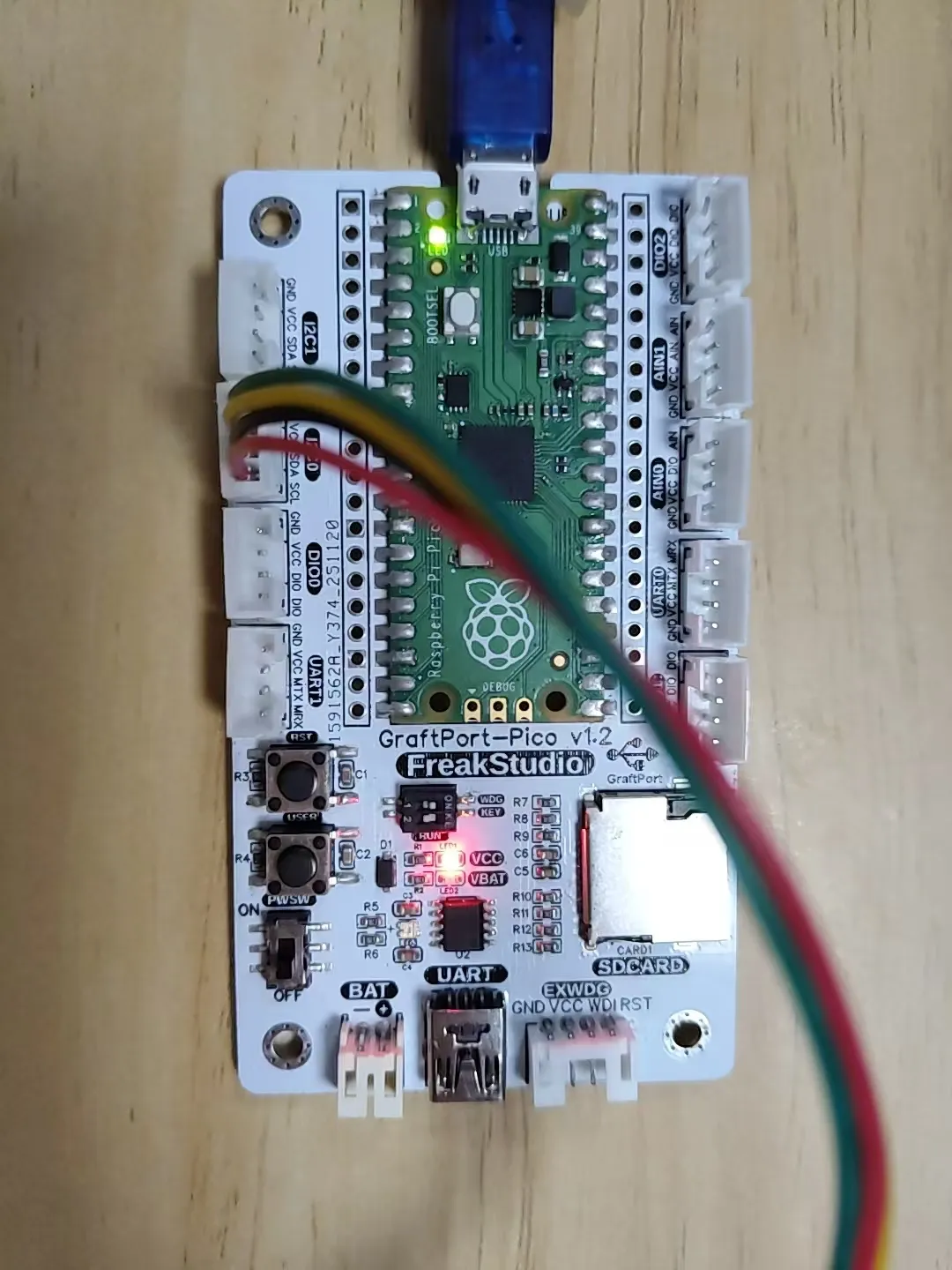
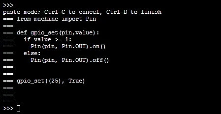
Advanced Example: Blink an LED
循环执行:
    将 输出引脚 25 设置为 高电平  # Turn on the LED
    延时 1 秒  # On for 1 second
    将 输出引脚 25 设置为 低电平 # Turn off the LED
    延时 1 秒  # Off for 1 second
Execution Result: The LED blinks regularly in the pattern of "on for 1 second, off for 1 second" — isn't that incredibly rewarding!
Tips
- The pin voltage level must match the device! For example, some LEDs require a low level to light up (which is the opposite of pin 25) — if it does not light up when set to a high level, try setting it to a low level;
- Do not connect high-power devices directly! The output current of the pins is very small, so high-power devices such as motors and bulbs cannot be connected directly. You need to use a relay/transistor together, otherwise the pins will be burned out~
✨ Interactive Quick Question
- Think about it: How should we set the pin to turn off a lit LED? (Answer: Set output pin 25 to a low level~)
- Quick Response Quiz: If a pin is set to high level, will it remain high after the development board is restarted? (Answer: No! The pin will revert to its default state, which is typically low level after reboot~)
- Try it out: Modify the delay time of the blinking program (e. g., 0.5 seconds) and see if the blinking rhythm of the LED speeds up~
Summary
- Pin Selection Block (pin): It serves as the foundation for all pin operations. It only specifies the number of the pin to be operated on without performing any actual action, and must be used in combination with other blocks;
- Output Pin Setting Block: Its core function is to control the pin to output high/low level, which can directly drive peripherals such as LEDs and buzzers, and the level state will be maintained until it is modified again or the device is restarted;
- Always check the pinout diagram of the development board before operating the pins to avoid selecting the wrong pins which may cause hardware damage or functional abnormalities.
3. Digital Input Reading Block (read digital input …, pull-up …)
Young makers, the output pins are for the development board to "send commands", while the digital input reading block is for the development board to "listen to commands" — it can read the "HIGH/LOW" state of a specified pin, just like when we touch a switch with our hand to tell whether it is "on" or "off", and it is most commonly used to read signals from peripherals such as buttons and switches~

Before we proceed, we first need to understand: digital input and pull-up resistors.
- What is numeric input?
A digital input has only two states: high level (1/true) and low level (0/false), which correspond to the "on/off" or "pressed/not pressed" states of a peripheral — for example, when a key is pressed, the pin is connected to GND (low level); when the key is released, the pin has no signal (if the pull-up resistor is not enabled, the state will fluctuate erratically).
- Why are pull-up resistors important?
If the pins of the development board are left floating (not connected to any signal), they will behave like "a person who cannot stand steadily", with their state jumping randomly (high for a while, then low for a while), which will cause the program to read incorrect values! After enabling the pull-up resistor:
- Enable pull-up (pull-up = enabled): The pin defaults to high level, and only goes low when connected to GND (e. g. when a button is pressed), delivering extremely stable readings;
- Disable pull-up (pull-up = OFF): The pin state depends entirely on external circuits; it will jump erratically when floating, so beginners should avoid using this setting as much as possible!
About "Pull-up Resistor"
pull-up = enable pull-up resistor
- When no signal is connected to the pin, it is read as high level by default;when connected to GND, it is read as low level
pull-up = off
- The pin status is entirely determined by the external circuit, but unstable readings may occur.
Chinese meaning: Read the digital input status of the specified pin ( digital input ) , and decide whether to enable the pull-up resistor ( pull-up ) according to the settings, and return the read result.
Specific example: The program reads the state of the pin connected to a button, and displays different information based on the read result.
将 输出引脚 25 设置为 高电平
读取 数字输入 引脚 25
显示 读取结果 为 高电平,不开启上拉电阻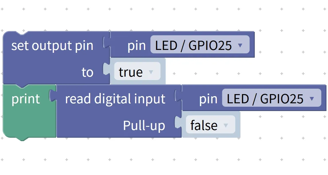
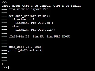
Execution Result: Displays "1", which indicates a high level.
Tips
- Pull-up resistors are a "must-enable for beginners"! Unless an external hardware pull-up/pull-down circuit is connected, you must enable this feature to avoid erratic jumping of the readings;
- Make sure to select "digital input pins"! All pins marked "GPIO" on the development board are available for use; do not select dedicated power pins (VCC, GND)~
✨ Interactive Quick Question
- Think about it: When the pull-up resistor is enabled, what will the pin read when the key is not pressed, 1 or 0? (Answer: 1! It only becomes 0 when the key is pressed.)
- Quick Quiz: Why do floating pins fluctuate erratically if no pull-up resistor is enabled? (Answer: The pin state becomes unstable, randomly switching between high and low levels, leading to incorrect readings in the program~)
4. ADC Input Reading Block (Read RPI Pico ADC Input …)
Young makers, digital inputs can only read "0/1"(on/off), but many signals in daily life are "continuously changing" — for example, the temperature rising from 20°C to 25°C, light shifting from bright to dim, or a potentiometer turning from left to right. These continuously changing signals are called analog signals, which the "brain"(CPU) of the development board cannot understand directly. They need to be "translated" into digital form by an ADC (Analog-to-Digital Converter), and this block is exactly the "translator" for the Pico development board!
Let's first get this straight: Analog Signal vs. Digital Signal
Signal Type | Features | Example | Can the development board read directly? |
|---|---|---|---|
analog signal | vary continuously and can take any value | Temperature, brightness, and potentiometer voltage | No, an ADC is required for translation. |
digital signal | Discrete, only 0/1 values | whether a key is pressed or not, and whether an LED is on or off | directly readable |
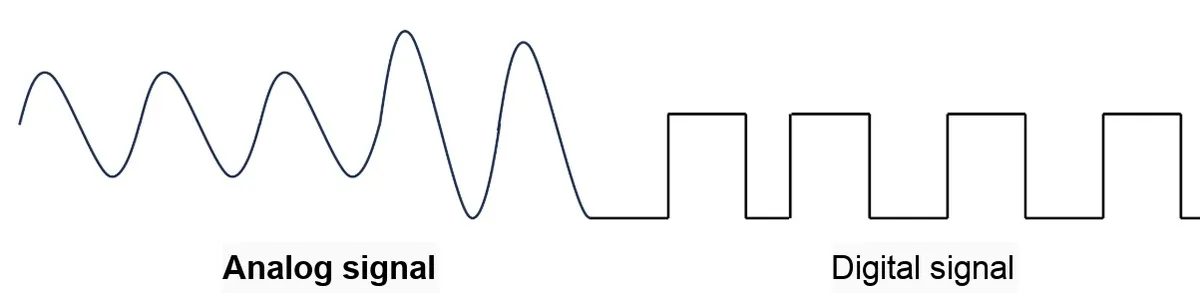
The function of the ADC: It converts analog voltages ranging from 0 to 3.3V into digital values between 0 and 65535 (this is the ADC precision of the Pico) — for example, 0V corresponds to 0, 3.3V corresponds to 65535, and 1.65V corresponds to 32768, which perfectly "translates" continuous signals!

Chinese meaning: Read Pico ( RPI Pico ) of the ADC analog input ( ADC Input ) , and return the current sampled value.
Specific example: Use the ADC channels available inside the Raspberry Pi Pico for reading, without connecting any external devices, which is only used to demonstrate the ADC reading process and the variation of the returned values.
读取 Pico ADC 输入 通道 29
显示 读取到的 ADC 数值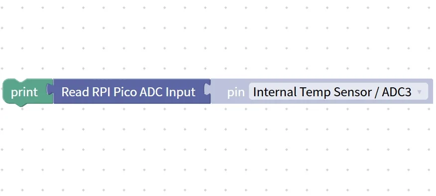
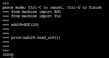
Execution Result: Display "32856". (The value may vary slightly depending on the chip, environment and operating status.)
5. PWM Output Configuration Block (PWM#: Pin, Frequency, Duty)
Young makers, previously the output pins could only be either "fully on or fully off", but what if we want the LED to brighten gradually or the motor to speed up slowly? PWM (Pulse Width Modulation) is the magic tool for this! It doesn't change the voltage; instead, it makes the pins "flash on and off rapidly" — when the flashing is fast enough, the human eye or connected devices will perceive the "brightness or rotation speed as changing continuously".
First, let's get this straight: the core parameters of PWM. There are 3 critical parameters for PWM, and none of them can be omitted.
- Pin (Pin): You must select a pin that supports PWM function (the development board pinout diagram will be marked with the "PWM" label), for example, pin 25 of the Pico;
- Frequency: The number of on-off cycles per second, with the unit being Hz. For LED control, select 1000~5000Hz (the flashing is so fast that it is invisible to the naked eye); for motor control, select tens of Hz;
- Duty (Duty Cycle): The proportion of time a signal stays at high level within one cycle. The duty cycle range of Pico is 0~65535:
- Duty = 0: All off (constant low level);
- Duty Cycle = 32768: Half brightness (high for half the time, low for half the time);
- Duty = 65535: Fully on (constant high level).
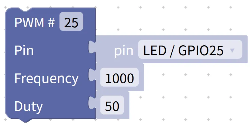
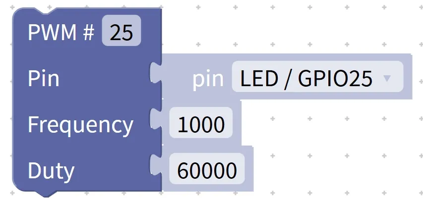
Chinese meaning: Output a PWM signal with the specified duty cycle (Duty) at the set frequency (Frequency) on the designated pin (Pin).
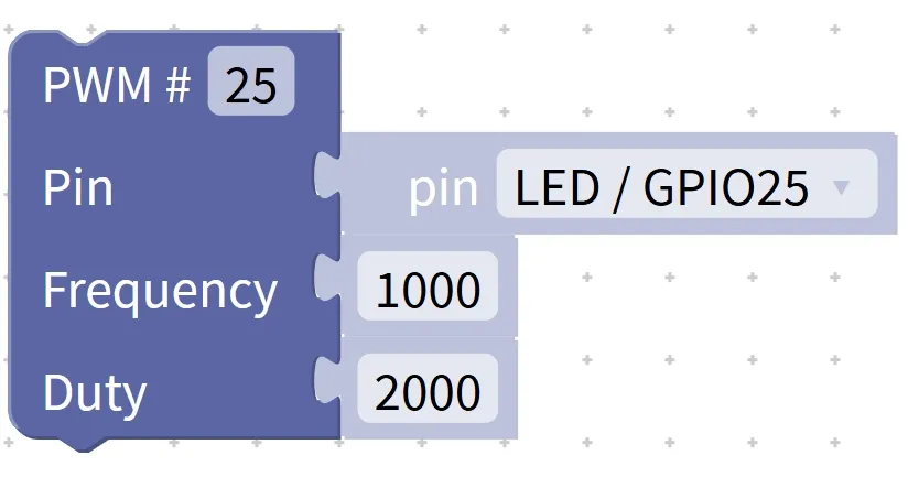
Specific example: Below, we will set the parameters of the same PWM pin twice, changing only the duty cycle to compare the differences in PWM output effects. The two settings use the same pin and frequency, with only the duty cycle being different, making it easy to observe the changes.
Set PWM output
  Pin is 25
  Frequency is 1000
  Duty is 2000
Set PWM output
Pin is 25
Frequency is 1000
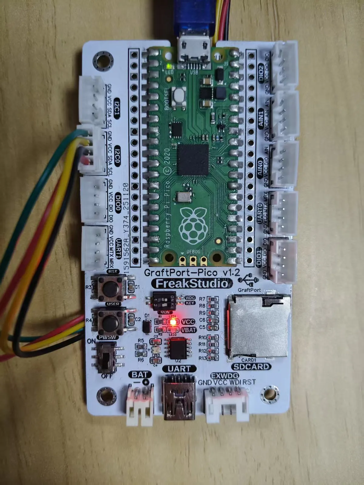
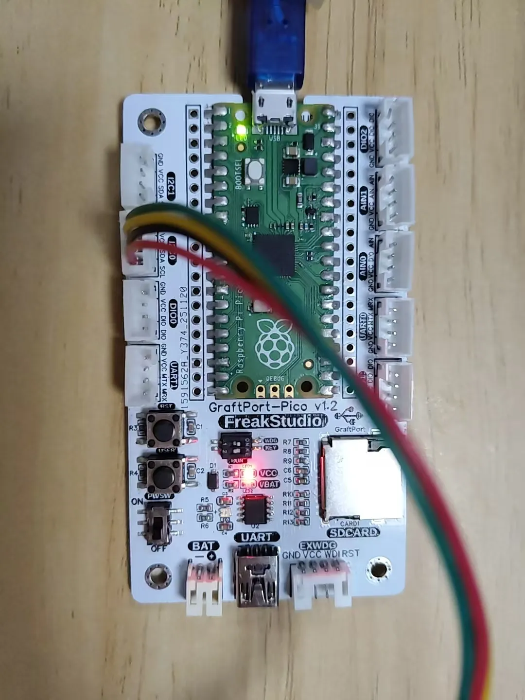
Duty is 60000Execution result: As can be seen, in the first example, the duty cycle is relatively small, the high-level duration is very short, and the LED displays as very dim, close to a faintly lit state; in the second example, the duty cycle is relatively large, the high-level duration increases significantly, and the LED displays as very bright, close to a fully lit state.
Tips
- Do not set the frequency too low! For example, if it is set to 10Hz, the LED will flicker obviously; it is recommended to set the frequency to ≥1000Hz for LED control;
- Do not exceed the valid duty cycle range! The duty cycle value for Pico ranges from 0 to 65535; any value set beyond this range will be automatically truncated to 65535~
✨ Interactive Quick Question
- Think about it: If you want the LED to be half-bright, what value should you set for Duty? (Answer: 32768, which is exactly half~)
- Quick Quiz: Does PWM change voltage? (Answer: No! It rapidly switches between high and low levels, and simulates "changes in brightness / rotation speed" by means of duty cycle~)
Summary
- Digital input reading block: Its core function is to read the status of pins 0 and 1. Enabling the pull-up resistor is a necessary step for beginners to prevent erratic readings, and this block is suitable for reading the status of buttons or switches.
- ADC Input Reading Block: Specifically designed to read continuously changing analog signals (temperature/brightness); the ADC of Pico returns a value in the range of 0 to 65535, and the higher the voltage, the larger the value;
- PWM Output Configuration Block: It enables precise control over LED brightness and motor speed by adjusting the frequency and duty cycle: the duty cycle determines the "intensity", while the frequency dictates the "flicker rate".
6. PWM Frequency Adjustment Block (PWM#… frequency…)
In the previous section, we learned to use PWM to control the brightness of an LED. However, at the same brightness level, some LEDs appear to "flicker" while others look very smooth — this is where the PWM frequency comes into play! The PWM frequency adjustment block is specifically designed to change "the number of on-off cycles per second"; it does not affect brightness or rotational speed, and only impacts whether the change appears smooth or not.

First, get this straight: The function of PWM frequency (it only affects "smoothness", not intensity)
frequency level | Features | Applicable Scenarios |
|---|---|---|
Low frequency (e. g. 10Hz) | The flicker decay is slow, and the obvious strobing of the LED is visible to the naked eye. | Rarely use (poor experience) |
Medium frequency (e. g., 1000 Hz) | It flashes out quickly, no flicker visible to the naked eye, and the brightness is smooth | Control LEDs and indicator lamps (most commonly used) |
High frequency (e. g., 10000Hz) | Extremely fast flicker with smoother transitions, but slightly higher power consumption | High-precision control (e. g., precision motors) |
Chinese meaning: set (set) the output frequency (frequency) of the specified PWM channel (PWM #), which is used to control the number of times the PWM signal changes per second.
Tips
- When controlling LEDs, the priority frequency range is 1000~5000Hz! This range delivers smooth performance without high power consumption, making it the optimal choice for beginners.
- Do not set the frequency too high! For example, if it exceeds 100000 Hz, it may go beyond the PWM capability of the pin, resulting in abnormal signals~
✨ Interactive Quick Question
- Think about it: If you want the buzzer to produce different tones, should you adjust the frequency or the duty cycle? (Answer: The frequency! The tone of a buzzer is determined by its frequency~)
7. PWM Duty Cycle Adjustment Block (PWM#… duty…)
If the PWM frequency can be likened to the "on-off rhythm", then the duty cycle is the "actual effect" — the duty cycle adjustment block is the core component for controlling LED brightness and motor speed: the higher the value, the longer the high-level duration, and the stronger the output.

Take Pico's duty cycle range of 0 to 65535 as an example:
- Duty cycle = 0 → all off (0% high level);
- Duty cycle = 16384 → 1/4 brightness (25% high level);
- Duty cycle = 32768 → Half brightness (50% high level);
- Duty = 65535 → Fully on (100% high level).
Chinese meaning: set (set) the duty cycle (of the specified PWM channel (PWM #) duty cycle duty) to control the output intensity.
Tips
- Duty cycle modification takes "effect immediately"! No need to wait for a delay, you can see the effect right after the modification;
- Do not exceed the valid duty cycle range! For Pico, the range is 0~65535; any value beyond this will be automatically truncated (e. g. if you set 70000, it will actually be processed as 65535)~
✨ Interactive Quick Question
- Think about it: If you want the motor to speed up from slow to fast, should you adjust the duty cycle or the frequency? (Answer: The duty cycle! The rotational speed is determined by the duty cycle~)
8. PWM Initialization Block (PWM#… init…)
Young creators, you must "power on" first before using PWM — just like you need to launch the game software before playing a game. The PWM initialization block is what "activates the PWM channel", enabling the specified pin to output PWM signals, and it is the very first step for all PWM-related operations!

If you directly adjust the frequency/duty cycle without initializing the PWM channel, the program will throw an error — this is because the pin has not been "activated" into PWM mode yet, just like trying to control a game character without even launching the game.
Chinese meaning: Initialize (init) to specify the PWM channel (PWM #).. . to prepare for subsequent PWM output.
Tips
- One PWM channel can only be bound to one pin! For example, if PWM#1 is bound to pin 25, do not bind PWM#1 to any other pin;
- Initialization only needs to be performed once! Just initialize it at the start of the program, there's no need to re-initialize every time you adjust the frequency or duty cycle~
✨ Interactive Quick Question
- Think about it: What will happen if you directly adjust the duty cycle without initializing PWM? (Answer: The program will report an error, and the pin will not output a PWM signal~)
9. PWM Release Block (deinit PWM #)
Young creators, remember to "shut down" after using PWM — the PWM release block is used to turn off the specified PWM channel, stop PWM signal output, and release the occupied system resources. It's just like closing the software after you finish playing a game so that it won't take up your computer's memory~
Core function: Stop PWM and release resources
- Stop Output: After being released, the pin will no longer output a PWM signal (e. g., the LED will turn off);
- Release resources: Return the system resources occupied by the PWM channel to the development board to make the program run more smoothly;
- For reuse: If you want to use this PWM channel again after releasing it, you need to reinitialize it.
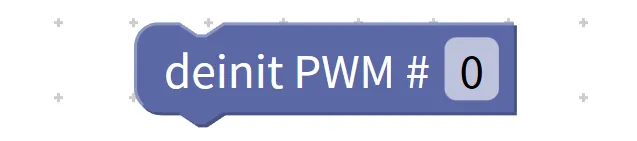
During the program running, when the PWM release block is executed, the system will turn off the specified PWM channel to stop the PWM output.
Chinese meaning: Release (deinitialize) the specified PWM channel (PWM#) and stop the PWM output of this channel.
Tips
- Always release PWM when it is not in use for a long time! For example, in battery-powered projects, releasing the PWM can save a small amount of power;
- The pin state after release is determined by the GPIO! If you want to keep the pin at a low level, you can add the operation "set output pin 25 to low level" after release~
✨ Interactive Quick Question
- Try it out: After releasing the PWM, if you directly adjust the duty cycle, will the LED light up? (Answer: No! Reinitialization is required~)
10. Pin Interrupt Block (External event (Interrupt on Input Pin))
An interrupt essentially refers to the act of interrupting. In daily life, we encounter this all the time:
- You are doing your homework when your phone suddenly rings. At this moment, you pause your homework to answer the phone.
- You are playing a game when the doorbell rings, and you immediately go to open the door.
In other words, an interruption will temporarily disrupt the work we are originally carrying out to handle an urgent matter; after the handling is completed, the program will return to the original work without losing the progress made beforehand.
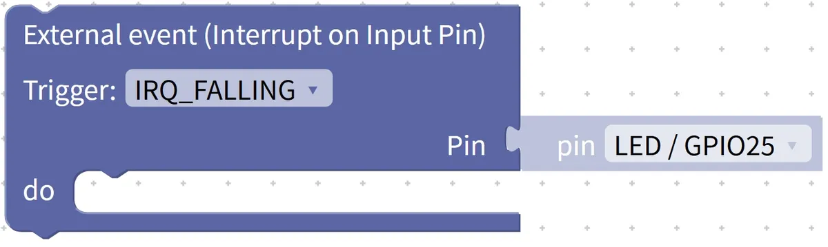
Young creators, previously when reading the status of a button, you had to "keep checking in a loop"(for example, reading once every 0.1 seconds). If the button was pressed quickly, the input might be missed. However, the pin interrupt block works in an "active listening" mode: as soon as the pin state changes (such as when a button is pressed), the program will immediately pause whatever it is doing to handle the button input, and then resume what it was doing afterward. It's just like when you're doing homework and hear the phone ring — you pick up the call right away, and get back to your homework after hanging up~
First, understand the core advantages of interrupts
Ordinary cyclic reading | Pin Interrupt |
|---|---|
Repeated cyclic inspection is required, and missed detection may occur | Active monitoring, with immediate response to status changes and no missed detections |
Occupies CPU resources (continuous inspection) | Does not occupy the CPU (the CPU performs other tasks when there is no change) |
Suitable for slow operations (e. g., long press) | Suitable for quick operations (such as single-click and double-click) |
Chinese meaning: When the interrupt input pin (Interrupt Input Pin) specified by the External event undergoes the set change, the corresponding program content (Interrupt) will be executed immediately.
Tips
- The code in an interrupt must be "short and fast"! Do not write infinite loops or long delays (e. g., 10 seconds), otherwise the main program will get stuck;
- Select the correct interrupt condition! For a key with pull-up enabled, select "High → Low"(triggered when pressed); if you select the opposite, there will be no response.
- Beginners commonly use "High → Low" or "Low → High"! These two are the most frequently used interrupt conditions, corresponding to the "press" and "release" actions of the button respectively~
✨ Interactive Quick Question
- Think about it: If you want "turn off the light when the button is released", what interrupt condition should you choose? (Answer: Pin 34 changes from low to high (button released) ~)
- Try it: change the delay in the interrupt to 5 seconds, and see if the main program will get stuck for 5 seconds~