
Contents
- 1. Why our kit is "not difficult to wire up"
- 2. Understanding the Main Control Board Interfaces
- 2.1 DIO Interface (DIO 0 / DIO 1)
- 2.2 AIN Interface (AIN 0)
- 2.3 I2C Interface (I2C 0 / I2C 1)
- 2.4 UART Interface (UART 0)
- 3. Wiring and Pin Selection: How to Find the Correct Pins from the Interface
- 4. General Rules for Interface Compatibility
- 4.1 First, categorize the interfaces
- 4.2 Quick Mnemonic for Mixed Interface Usage (Remember in One Sentence)
- 4.3 Practical Application in Our Project
- 5. General Wiring Procedures
- 6. Common Questions for Beginners
1. Why our kit is "not difficult to wire up"
In traditional electronics experiments, students often need to connect DuPont wires one by one, each of which corresponds to its own power line, signal line and ground line. If any connection is made incorrectly, the program will fail to run, and the modules may even be easily damaged. For beginners, this is a major difficulty, which causes many people to give up right at the start.
To make learning easier, our kit features a unified port standard design. Simply plug each module into its corresponding interface to complete the wiring — no need to memorize the function of each wire, nor worry about the positive and negative poles of the power supply.
Simply put: for wiring, only the interface type matters; for programming, only the pin number matters.
This design offers three key advantages:
- Lower the learning threshold
Beginners can quickly get started with experiments without needing to understand complex circuits. - Reduce misoperation
The module interfaces feature clear specifications, making it extremely difficult to plug in incorrectly even when wiring for the first time. - Focus on functional learning
Students can direct their attention to the functions of the modules and the experimental results, instead of getting caught up in figuring out how to connect the wires.
With this design, you can get started without worry and focus on the operation and experimental logic.
2. Understanding the Main Control Board Interfaces
The main control board has reserved fixed interfaces for commonly used modules. We don’t need to guess the wiring on our own; as long as we get familiar with the types and purposes of these interfaces, we can quickly get started with wiring.
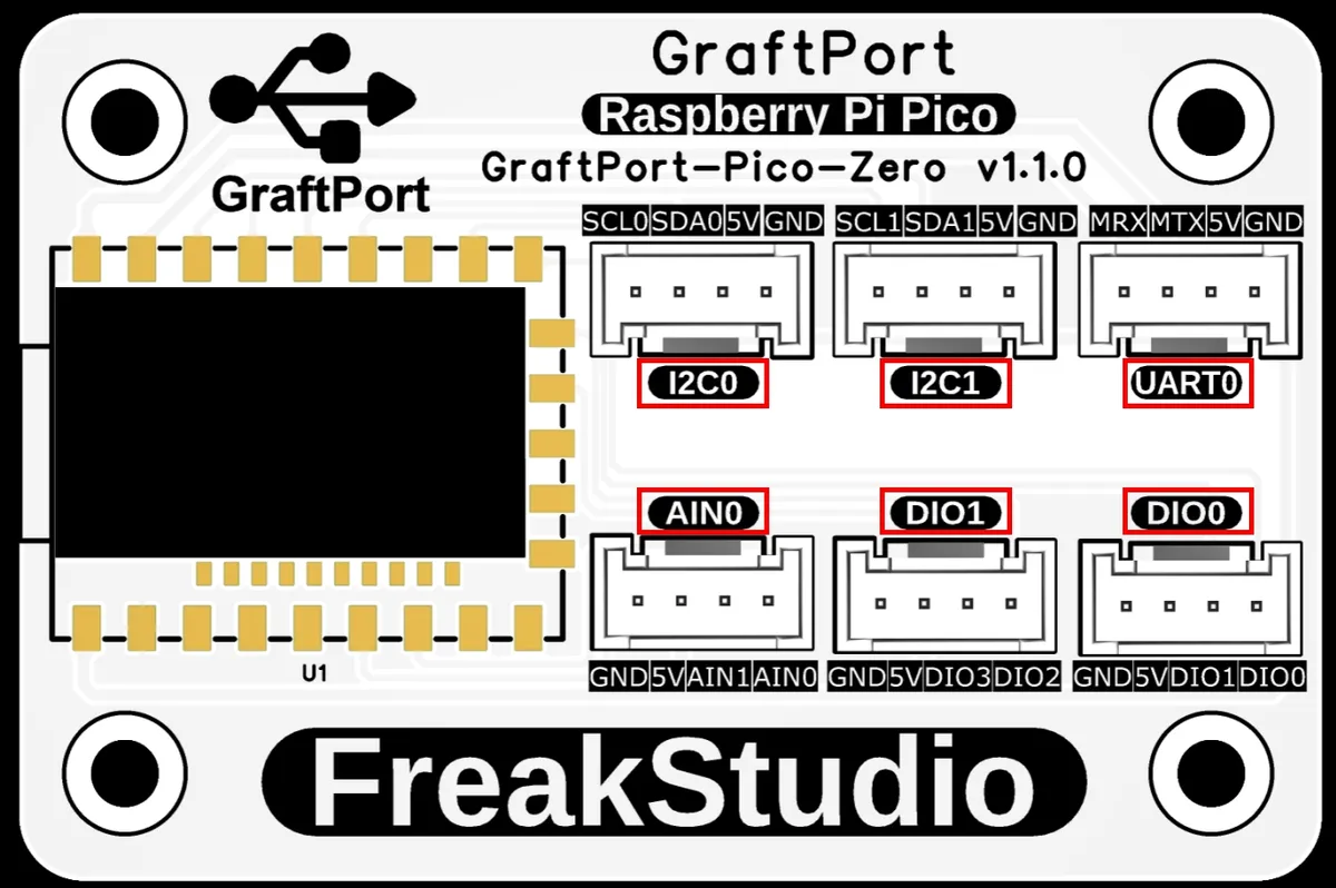
2.1 DIO Interface (DIO 0 / DIO 1)
- Function: Connects on/off type modules.
- Features: There are only two states — present/absent, on/off.
- Common Modules:
- Mechanical Key Module
- Piranha LED Light
💡 Memory Tip: Most modules that involve "press, light up, beep, trigger" are connected to DIO.
2.2 AIN Interface (AIN 0)
- Function: Reads continuously varying values.
- Features: Suitable for modules whose "value changes dynamically", such as brightness, smoke concentration, flame intensity, etc.
- Common Modules:
- Light Intensity Sensor Module (GL5516)
- MQ-2 Smoke Sensor Module
- Flame Sensor Module (PT334)
💡 Memory Tip: Whenever a value is read out loud, follow it with AIN.
2.3 I2C Interface (I2C 0 / I2C 1)
- Function: Connect the I2C communication module.
- Features: Simply plug into the interface, no need to distinguish each cable.
- Common Modules:
- 0.96-inch SSD1306 OLED Display Module
💡 Memory Tip: Most modules that function as "display, communication, or data transmission" are connected via I2C.
2.4 UART Interface (UART 0)
- Function: Connect the serial communication module.
- Note: This is for your reference at the beginner stage and will be covered in subsequent advanced modules.
💡 Beginner Tip: Beginners don't need to perform any operations for now; just be aware that this exists.
3. Wiring and Pin Selection: How to Find the Correct Pins from the Interface
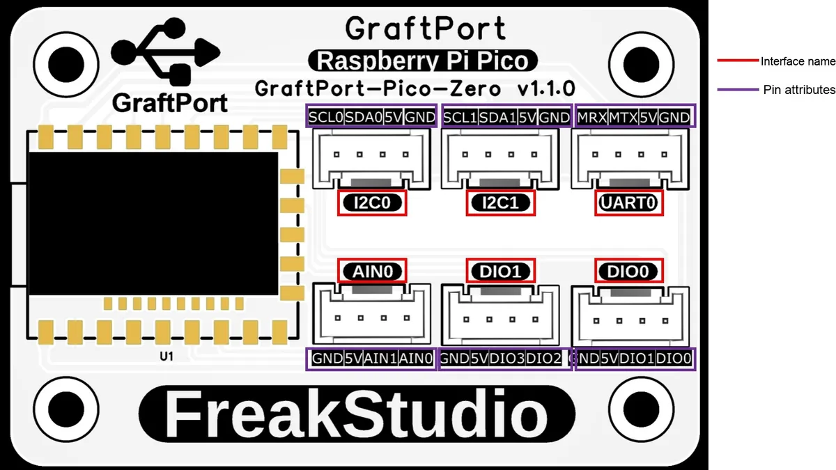
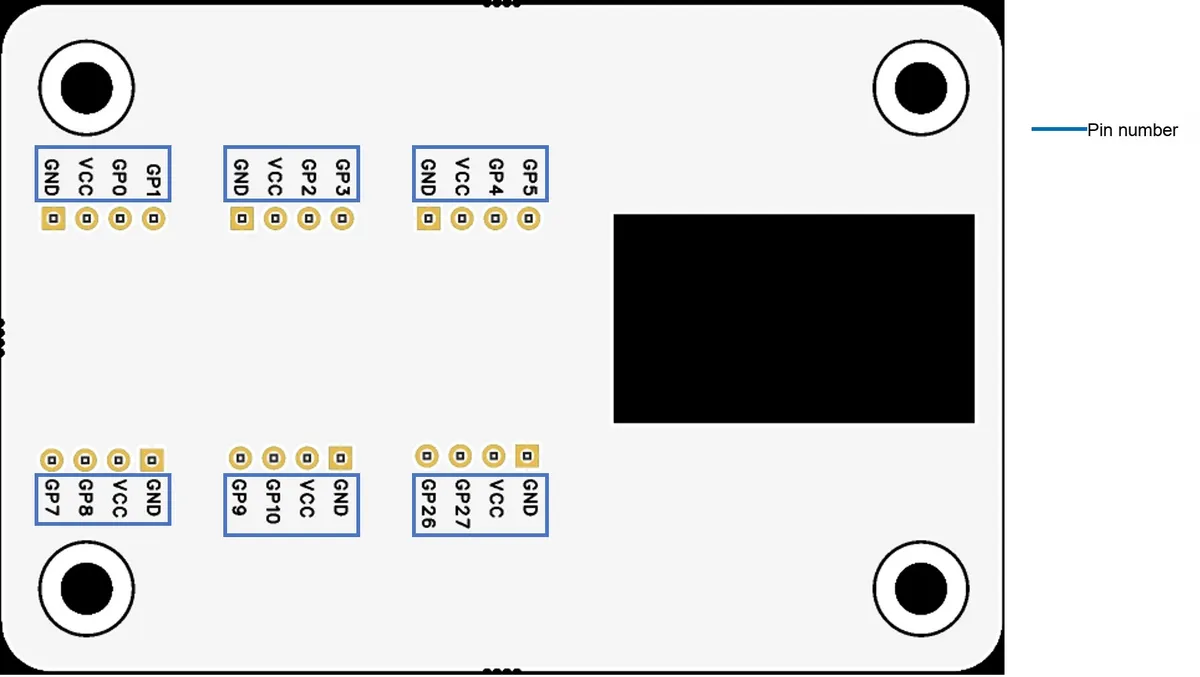
In our kit, you only need to align the module with the interface on the main control board and plug it in, which simultaneously completes power supply and signal connection. That's why when wiring, you only need to "plug into the matching interface" instead of connecting power cables one by one.
However, after connecting the module properly, there is still a crucial step to complete, which is to select the correct pin number in the program.
This is because: when the main control board runs a program, it cannot identify "whether you have plugged into the DIO 0 or AIN 0 interface"; what it can actually control and read are specific pin numbers one by one (such as GP5, GP7, etc.). Only when the pin number selected in the program matches the pin actually connected to the module can the main control board correctly control the module or read data.
In our kit, to ensure that all modules can have unified interfaces and unified wiring methods, we have all adopted the 4-wire interface specification. The advantage of this approach is that the interface form is completely consistent, making it less likely for beginners to make mistakes when wiring, and there is no need to distinguish between positive and negative power supplies.
It should be noted that:
Although the interface has 4 wires, the module itself does not necessarily actually use all 4 wires.
For many basic modules, only the following are required in actual operation:
- Power Supply (VCC)
- Ground (GND)
- 1 signal line
To maintain interface consistency, 2 signal pins are still reserved at the interface position. However, in many modules, only one of these signal pins is actually connected to the module circuit, while the other is unused inside the module. This unused signal pin is usually marked as NC on the module.
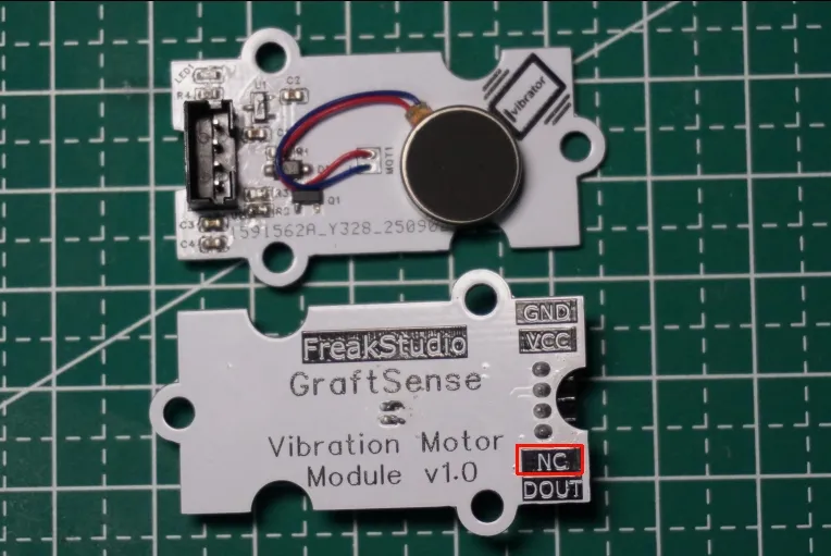
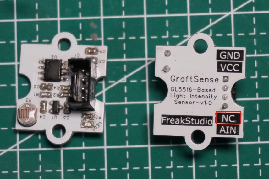
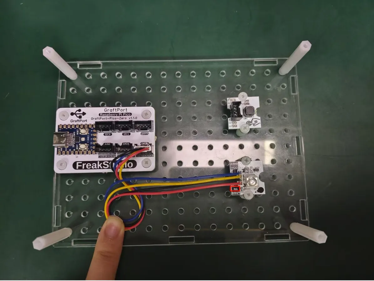
Therefore, in the program, it is not the case that "the two signal pins on the interface can both be selected arbitrarily". For modules using a 4-wire interface, we need to check the pin markings on the module to find out which signal pin is actually connected to the module's circuit.
If the module is marked as NC, it indicates that this pin is not used inside the module, so do not select the GP number corresponding to this pin in the program. In the program, you only need and can only select the pin that is actually used by the module.
This is also why sometimes you will find that: the same interface position corresponds to two GP pins, yet the module can work properly as long as only one of them is configured in the program.
Be sure to make a clear distinction between these two matters:
- Interface Name: DIO 0, AIN 0, I2C 0 (for use when wired)
- Pin Number: GP5, GP0, etc. (for programming use)
The relationship between them is as follows:
Interface location → Check the silkscreen → Obtain the pin number → Select the pin in the program
4. General Rules for Interface Compatibility
Young makers, when you're building with blocks, have you ever run into a situation where you don't have enough of the small square blocks you need, but there are some long blocks with wheels left unused? Well, the interfaces on our development boards work exactly the same way!
When working on an integrated project where you want to connect several LEDs, buttons and sensors at the same time, you may find that: "The DIO interfaces I need are all used up, but the I2C interface is still idle!" or "There aren't enough AIN interfaces, but there are still spare DIO interfaces!"
Don't panic. In this section, we'll explain in a super straightforward way: whether those vacant interfaces are usable, and how to use them without causing damage.
4.1 First, categorize the interfaces
We can categorize the interfaces of the main control board into three groups based on their functional complexity:
Interface Type | analogy | What you can do |
|---|---|---|
🌟 All-in-One Interface I2C, UART | Multi-functional pen: It can be used for writing, drawing, and as a ruler. |
|
⚡ Half-Energy Interface AIN | Mechanical pencil: It can be used for writing, and also functions as an eraser. |
|
📝 Basic Interface DIO | Regular pencil: only for writing | It only supports basic digital functions, such as controlling the on/off of LEDs, detecting key presses, and PWM output. |
4.2 Quick Mnemonic for Mixed Interface Usage (Remember in One Sentence)
High energy can be applied for low-demand purposes, but low energy can never be applied for high-demand purposes; half energy can be utilized for full-demand scenarios, but full energy can never be utilized for half-demand scenarios
In plain terms, this means:
- ✅ Interfaces with higher capability (full-capable / semi-capable) can be temporarily used as interfaces that "only handle trivial tasks"
- ❌ An interface only capable of handling trivial tasks must never be used as one for "major tasks"
4.3 Practical Application in Our Project
- Universal Interface (I2C/UART) → Can be used as basic interfaces (DIO/AIN) ✅
For example:
- All your DIO ports are occupied by LEDs, leaving no space for the buzzer → you can plug the buzzer into an available I2C port instead.
- Reason: The buzzer only requires a basic "on/off" signal, and the I2C interface inherently supports this function, just like a multi-functional pen being temporarily used as an ordinary pencil.
- Analog Interface (AIN) → Available as Digital Input/Output (DIO) ✅
For example:
- Your DIO ports are all used up, but there are still unused AIN ports available → you can plug the LED into an AIN port.
- Reason: LEDs only require digital signals for "on/off" control, and the AIN interface can both read analog values and output digital signals — just like using a mechanical pencil as a regular pencil on a temporary basis.
- Basic Digital Input/Output (DIO) → Do NOT use as a semi-functional / full-functional interface ❌
For example:
- You've run out of I2C interfaces and want to plug the OLED display into the DIO port → No way!
- You've run out of AIN ports and want to plug your microphone into a DIO port → No way!
- Reason: OLED requires the advanced "synchronous communication" function of I2C, the microphone needs the "analog value reading" function of AIN, which the DIO interface simply cannot deliver — just as a regular pencil cannot function as a multi-functional stylus.
Want to use a certain interface as something else | Is that okay? | Example |
I2C → DIO | ✅ | Connect the buzzer to the I2C interface |
UART → DIO | ✅ | LED connected to UART interface |
AIN → DIO | ✅ | Insert the key into the AIN interface |
DIO → AIN | ❌ | Plug the microphone into the DIO interface |
DIO → I2C | ❌ | Insert the OLED display into the DIO interface |
AIN → I2C | ❌ | OLED display connected to AIN interface |
In the basic experiment and preliminary learning stages, there is no need to consider interface reuse issues, and you only need to wire normally according to the interface type. The flexible use of interface capabilities mainly occurs in later-stage comprehensive projects and scenarios with a large number of modules.
Friendly Reminder
- Don’t mess around unnecessarily in daily use: when conducting a single small experiment, just plug the modules into their corresponding interfaces — for example, plug the LED into DIO, the microphone into AIN, and the OLED into I2C — this is the most stable approach.
- Use only when there is a shortage of interfaces: Only when working on an integrated project and running out of available interfaces should you apply this clever trick of "using a high-spec component for a low-demand scenario".
- Confirm the interface is idle: When using a universal interface (I2C/UART) as the base interface, make sure that this interface is not connected to any other advanced modules (such as an OLED display), otherwise a conflict will occur.
✨ Interactive Quick Question
- Quick Response Quiz: I want to connect the 5th LED, but all DIO ports are already used up while the AIN ports are still vacant. Can I plug the LED into an AIN port? (Answer: Yes, you can!)
- Just think: You want to connect a second OLED display, but all the I2C interfaces are already used up. Can you plug it into a DIO interface instead? (Answer: No, you can't!)
5. General Wiring Procedures
Step 1: Define the module interface
First, check the module description to confirm which category of interface the module belongs to, such as DIO, AIN or I2C. This step is to determine which interface area on the main control board the module should be plugged into.
Step 2: Insert the module into the correct interface
Insert the module into the corresponding marked interface on the main control board according to the module type. As the interfaces are designed in a standardized manner, there is no need to connect a separate power supply cable or distinguish between positive and negative poles — simply align the module with the interface and insert it into place. This step addresses the question of "where to connect the module".
Step 3: Check the pin number corresponding to this interface
Check the silkscreen on the back of the main control board, and find the pin number corresponding to the interface you just used, such as GP5 (GPIO5), GP7 (GPIO7), etc. This number is the pin number that needs to be used in the program. This step solves the problem of "which pin the program should use to control the module".
Step 4: Select this pin number in graphical programming
Open the graphical programming software, select the pin number you just confirmed from the corresponding blocks, and the main control board will be able to control the module or read data from it via this pin.
As long as the interface used for module wiring, the pin number marked on the silkscreen of the main control board, and the pin selected in the program are consistent with one another, the module can work properly.
Important Reminder: If you select the wrong pin in the program, the module will not be damaged, it just won't work.
6. Common Questions for Beginners
Q: The module isn't working. Did I connect it incorrectly?
A: In most cases, this is caused by selecting the wrong pin in the program; just check the silkscreen to confirm.
Q: Can modules be plugged into any interface freely?
A: No, they must be plugged into the interface of the corresponding type.
Q: Will wrong connection burn out the module?
A: The interfaces of this kit are standardized, so the module will not be damaged as long as beginners operate normally.
Q: The DIO ports on the project are insufficient while the I2C ports are idle. Is it possible to connect LEDs/buttons to the I2C ports? Conversely, if the I2C ports are insufficient, can DIO ports be used as a replacement?
A: I2C ports can be used as DIO ports, but DIO ports cannot replace I2C ports! This is because advanced interfaces can be downgraded to function as low-level interfaces, while low-level interfaces cannot be upgraded to replace advanced interfaces.