
Contents
- 1. What is graphical programming
- 2. What exactly do we need to control?
- 2.1 Super Brain – The Main Control Board
- 2.2 "Sensory Organs" and "Limbs" — Various Functional Modules
- 2.3 Team Commander: Graphical Program
- 3. Introduction to Graphical User Interface
- 3.1 Block Area (Blocks)
- 3.2 Device Area (Device)
- 3.3 Program Execution and Code Area (Console)
Hey, all you young creators! Today we’re going to unlock a super-duper cool skill — using colorful little building blocks to get real hardware like robots, tiny lights, and little cars to do exactly what you want!
First, let's imagine a scenario: you say to a small robot, "Move forward!" "Turn on the red light!" and it does exactly as you tell it right away — doesn't that feel like magic? In today's lesson, we're going to learn this "magic", and it's not hard at all!
Here's a super important little secret to keep in mind: those colorful little shapes we drag around on the computer are not just random doodle toys! Each and every one of those shapes is a "command note" sent to the hardware — just like the note you write to your friend saying "let's hang out after school", once our hardware receives it, it will follow through on it!
Finally, the complete set of "command notes" we put together will transform into a "little magic package" and reside in the "brain"(main control board) of the hardware. From then on, the hardware will obediently follow our instructions to complete actions step by step!
1. What is graphical programming
Graphical programming, to put it bluntly, is "writing programs by stacking building blocks"!
Imagine the building blocks you play with: each block has its own purpose — some are wheels, some are windows, and others are roofs. When you put them together in order and following the rules, you can build toy cars, small houses, and grand castles!
The "building blocks" of graphical programming work the same way:
- Each colored "building block" corresponds to a specific command (such as "turn on the light", "start the motor", "wait for 2 seconds");
- Put these building blocks together in order, and you can form a complete program;
- Compared with the "typing and coding" tools that mom and dad use for work, it doesn’t require memorizing complicated English words or memorizing strange symbol rules — you only need to figure out what each building block does, piece them together like Lego, and you can write a program that makes hardware do what you want!
Let me tell you a little secret: when primary and secondary school students learn block-based programming, it’s not about becoming a "typing pro" — it’s about building three incredibly powerful skills:
- Understand the magical logic of "I issue a command → hardware executes it → I see the result"
- Learn to think like a little detective, and work through problems step by step (for example, "Why won't the little car move? Oh! I forgot to assemble the 'starter motor' bricks!")
- Experience firsthand the joy of "controlling real devices with code" — making a tiny LED light up, getting a small robot car to move; that sense of accomplishment is even more thrilling than playing video games!
Mini Interaction Session
- Raise your hand to answer: What exactly are the "blocks" in graphical programming? (Answer: They are instruction slips for hardware!)
- Think: What do you most want to command the hardware to do through programming? Make a tiny light flash in rainbow colors, or make a little car drive around the table in a full circle?
2. What exactly do we need to control?
Hey, young creators! The colorful block-based program we’ve built together doesn’t work all alone, you know. It needs to team up with its little buddies to make something amazing happen! It’s just like how you can’t play Eagle and Chickens by yourself — you need teammates to join in the fun!
In this course, the "partner team" of a program consists of 3 core members, each with a distinct role and none dispensable! Let's get to know them one by one, just like making new friends.
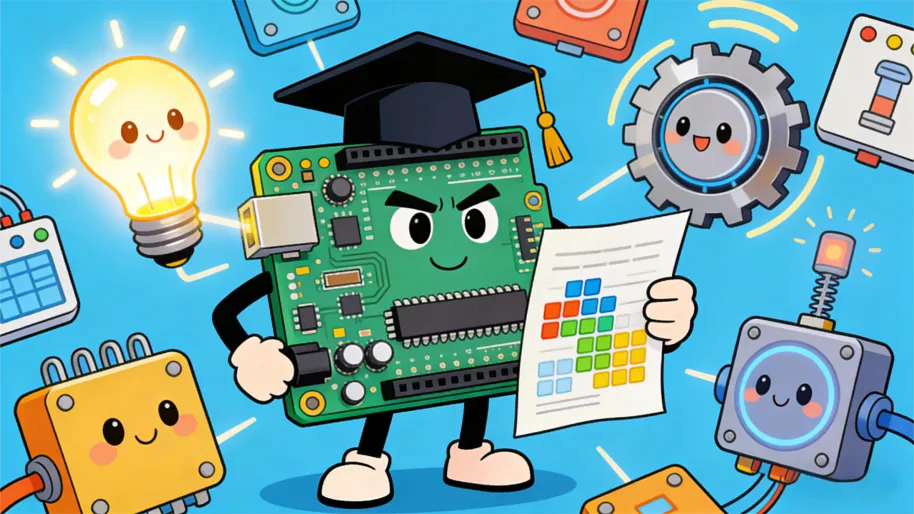
I. Core of the Team: Main Control Board — Get to Know This "Super Brain" First
Everyone, touch your own little head first~ Our heads can think and command our body to move, and the main control board is the "super brain" in the hardware team! Later we will specifically talk about its specific identity — the Raspberry Pi Pico main control board, just remember that it is the core of the team for now!
It has two core functions: first, to "read" and understand the block program instructions we piece together, and second, to send commands to other components. We will explain in detail later on how it specifically runs programs and sends instructions!
Tip: The main control board is just like the monitor in a class: it not only follows the teacher's instructions (which correspond to our programs), but also coordinates the classmates (namely the "functional modules" we will talk about later) to get things done~
II. Team Assistant: Functional Modules – "Perceptive Sensors + Agile Manipulators"
The brain alone isn’t enough! To get tasks done, we also need "sensory organs" and "hands and feet" — and that’s exactly what functional modules are for. Later on, we’ll take a close look at specific modules like LED lights and buttons, but for now, let’s first get clear on their two core categories of responsibilities.
They fall into two major schools of thought:
- "Sensory faction": Our eyes and ears, for instance, can perceive the surrounding conditions (such as temperature and brightness) — we’ll explain how the specific sensor modules work later~
- "Hands and Feet Components": Just like our hands and feet that can perform specific actions (such as turning on lights, rotating motors, producing sounds), we will get to know modules like LED lights and buzzers one by one later~
III. Team Commander: Graphical Program – "Exclusive Operation Manual"
Finally, there's the graphical program we assemble! It's like a "command script" tailored specifically for the team, whose core function is to tell the main control board "what to do and when to do it". We'll learn how to assemble this script in detail later, for now just remember that it acts as the "commander" of the team~
Once we "load" the program into the main control board, it will sequentially instruct the sensory module to perceive information and the limb modules to perform actions. As for how to specifically set the sequence and send commands, we will walk you through that step by step in the subsequent detailed breakdowns!
The super fun interactive session is here!
- Raise your hand to answer quickly! Who is the "super brain" in the hardware team? (Answer: Main control board!)
- Just think: If I want the car to stop when it "sees" an obstacle ahead, which type of functional module do I need to use? Is it the "sensory type" or the "motor type"? (Hint: "Seeing an obstacle" means perceiving the situation~)
- Group discussion for 10 seconds: Which members of our team do you think need to work together to complete the task of "making the small light turn on automatically when it gets dark"? (Please have the group representative speak~)
- Quick question: What does the graphical program we built work like? (Answer: A custom operation manual!)
To sum up: we’ve now got to know the three core members of the hardware team — the main control board, the functional module, and the graphical program, and have a general idea of their respective responsibilities. Next, we’ll dive into each of them one by one to see what each member specifically looks like and what special capabilities they have!
2.1 Super Brain – The Main Control Board
Earlier, we got to know the "super brain" of the hardware team — the main control board. Today, let's take a close-up look at its specific identity: Raspberry Pi Pico main control board! It acts like a dedicated little butler, taking care of everything related to program operation and instruction sending for us~
I. First, let’s take a look at its "little appearance"
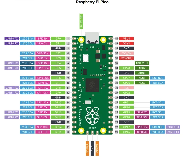
Everyone, take out the Pico main control board on the desk and follow the teacher to find these "small marks":
- "Compact Form Factor": It has a square, boxy shape, just slightly larger than an eraser, making it easy to mount on small vehicles or mini robots and take anywhere you go~
- "Golden Dots": There are two rows of small golden protrusions along the edge of the board, which act as its "little hands"(pins) — they are specially designed to connect and work with components like LED lights and sensors.
- 「Name Identifier」: The text "Raspberry Pi Pico" can be seen on the front, which is its exclusive name, just like how a school name is printed on our school uniform~
- 「Small Switch/Interface」: There is also a micro USB interface (for connecting to a computer), and some boards are additionally equipped with a small switch, which serve as the "power input port" and "communication port" of the device~
II. Unveiling Its "Superpowers": Why Is It Called a "Super Brain"?
We already know that it has two core functions, so today let's break these functions down to see exactly how it works:
- Superpower 1: "Read and execute" our commands. When we connect the block program we have assembled on the computer to the Pico via a USB cable and click Run, it will immediately "read" every instruction in the program and execute them in sequence.
- Superpower 2: Send "Precise Commands" to Your Little Buddies When the program runs, Pico will use the "little golden hands"(pins) on its edge to send commands to functional modules like LED lights and motors. For example, if the program says "turn on the red light", it will transmit this command to the LED light module accurately through the corresponding pin, with no chance of sending it to the wrong place! It's just like a class monitor who conveys the teacher's instructions precisely, making sure every classmate knows exactly what they need to do~
- Superpower 3: Receive "feedback" from your little buddies. It doesn't just send out commands — it can also receive information from functional modules through its pins! For example, when a temperature sensor detects that "it's getting hot", it will send this information to the Pico, which then decides according to the program "whether to turn on the fan or not". This is just like how our brain receives information from what our eyes see and our ears hear, then decides what to do next~
III. How to "Make Friends" with It?
To get Pico to work for us, you only need three steps to establish a "working relationship" with it and smoothly activate the command mode~
- "Step 1: Establish Connection" – Use a USB cable to connect the Pico to your computer. At this point, the computer will be able to "detect" this small board, and we can then transfer the assembled program to it~
- "Step 2: Supply Power" After connecting the USB cable, the Pico will get power (just like putting batteries in a toy car), and there's no need to install extra batteries at all — isn't that super convenient?
- "Step 3: Deliver the 'Operation Manual'": Open our graphical programming software, click "Run" for the assembled block program, and you can watch the Pico execute step by step. This step is just like handing the "instruction note" we wrote to the little housekeeper; once delivered, it will know exactly how to get the work done!
Interactive Mini-Class
- Observation and Quick Response: What are the tiny golden dots on the edge of the Pico main control board called? (Answer: Pins / little hands!)
- Hands-on Task: Locate the "Raspberry Pi Pico" label and the USB port on your Pico board, then hold it up to show the teacher~
- Quick reflection: What would happen if Pico didn't have the superpower of "receiving feedback"? (Hint: For example, if the temperature sensor tells it that it's hot but it can't receive the message, it won't be able to turn on the fan~)
To sum up: the Raspberry Pi Pico main control board is the "core little manager" of our hardware team. It has the superpower to run programs, issue commands and receive feedback, and you only need to connect it to a computer with a USB cable to work with it~ Next, we will learn how to transfer programs to it, so that it can direct other components to work!
2.2 "Sensory Organs" and "Limbs" — Various Functional Modules
We just got to know the "super brain" of the hardware team — the Pico main control board, and today let's meet its great partners — functional modules! If the main control board is the "brain", then these functional modules are the "senses" and "limbs" of the team, which are specially designed to handle specific tasks. Without them, no matter how powerful the main control board is, it cannot complete practical tasks, just like we can't draw or run if we only have a brain but no eyes, hands or feet!
I. First, let’s understand two basic concepts: "input" and "output"
Although there are many types of functional modules, they essentially fall into two broad categories: the "input faction" and the "output faction". Do these terms sound a bit abstract? Don't worry, once the teacher explains them with real-life examples, you'll get it right away!
- What exactly is "input"? — It means sending information to the brain. Just like how your eyes see "it's getting dark" and your ears hear "the school bell ringing", then pass these pieces of information to your brain. The "input module" works by collecting external information (such as temperature, brightness, or whether a button has been pressed) and transmitting it to the main control board, which acts as the "brain". To put it simply: input = "reporting information to the brain"!
- What exactly is "output"? — It means acting in accordance with the brain's commands, just like when your brain tells you to "raise your hand" or "say the answer". The "Output Faction" module works by receiving commands from the main control board and performing specific actions (such as lighting up, making sounds, or spinning). To put it simply: output = "getting the job done" as instructed!
Brief Summary: The input module is responsible for "sensing + reporting", and the output module takes charge of "executing + operating". When the two work in coordination with the main control board, they can fulfill all kinds of tasks!
II. Get to Know Common "Output-Focused" Helpers
These modules are the "hands and feet" of the hardware team. They spring into action immediately upon receiving instructions from the main control board, and we can directly see and hear the results of their work in our daily lives~
- LED Light Module —— The Glowing "Signal Indicator" This is the most common output module, just like the tiny decorative lights we see in daily life! Its function is to turn on, turn off, or flash as instructed. For example, when the main control board sends the command "turn on the red light", it will immediately light up the red LED; when receiving the command "flash 3 times", it will cycle through on and off three times. Common variants include red, green and blue LEDs, and they can also be combined to form rainbow lights~
- Buzzer Module —— The Singing "Little Speaker" Its job is to produce sounds as instructed! For example, when the main control board sends the command to "play Happy Birthday", it will play the melody; when it receives the command to "beep once", it will emit a clear prompt tone. Some buzzers can only produce fixed sounds, while others can play all kinds of music — super fun~
- Motor Module —— The spinning "little motor" It acts as the "strongman" of the team, responsible for driving other components to rotate! For example, when installed on a small car, once the main control board sends the command "spin forward", it will drive the wheels to turn and the car will move forward; when the command "slow down a little" is sent, it will reduce its speed. There is a similar motor hidden inside the remote-controlled cars we usually play with~
III. Getting to Know Common "Input-Style" Helpful Tools
These modules serve as the "sensory organs" of the hardware team. They quietly perceive the surrounding conditions and then transmit the information to the main control board. Though they are not particularly "noticeable", they act as the "intelligence agents" within the team; without them, the main control board would be completely "blind and deaf to its surroundings".
- Button Module —— A pressable "switch" It's just like the light switch at home, or the "start button" on a toy car! When you press the button, it sends a signal of "I'm pressed!" to the main control board; when you release it, it sends a signal of "I'm released!". For example, we can program it: when the button is pressed, the LED lights up; when the button is released, the LED turns off~
- Temperature Sensor Module — A "Mini Thermometer" That Detects Hot and Cold Its function is to sense the ambient temperature and then transmit the information of "what the current temperature is" to the main control board. For example, when the temperature exceeds 30 degrees Celsius in summer, it will inform the main control board that "it's hot", and the main control board will then instruct the fan module to start running; when the temperature drops below 10 degrees Celsius in winter, it can command the heating module (similar to a small warming lamp) to work~
- Light Sensor Module — The "Little Eye" That Detects Brightness and Darkness Just like the human eye that can tell day from night, it perceives the ambient brightness and transmits the information of "it's very bright now" or "it's very dark now" to the main control board. For example, when it gets dark at night, it informs the main control board, which then instructs the LED light to turn on automatically; when it gets bright during the day, it commands the LED light to turn off — it’s super smart~
Have you guys noticed something? Modules with the word "sensor" in their names, such as temperature sensors and light sensors, basically all fall into the "input category"!
Then why do all sensors belong to the input category? Because the core job of a sensor is to "perceive changes and information in the surrounding environment" — for example, detecting whether the temperature is rising or falling, whether the light is getting brighter or dimmer, or whether it has been touched, then transmitting all this perceived information intact to the main control board, which acts as the "brain". A sensor is only responsible for "collecting and reporting information" and will not take any action on its own (it won't light up by itself, nor will it rotate on its own), so it perfectly matches the function of the input category, which is to "send information to the brain".
IV. How do modules "cooperate" with the main control board?
How do these little helpers work with the Pico main control board? Actually, it's super easy — just like how we team up and hold hands with our buddies:
Use Dupont wires (a type of dedicated connecting cable) to connect the functional modules to the "little golden hands"(pins) on the Pico main control board, so that they can exchange information with each other! For example, if you connect an LED module to a pin on the Pico, the Pico's commands will be transmitted to the LED through that pin; if you connect a temperature sensor to a pin, the temperature data detected by the sensor will be sent to the Pico via the pin~
Besides, each module has its own "dedicated interface", so there's no risk of connecting them incorrectly! The teacher will guide you to make the connections hands-on later, for now, just remember that you can get them to work together by connecting the pins with wires~
Interactive Mini-Class
- Quick-response quiz: Is the LED light module an "input type" or an "output type"? Why? (Answer: Output type! Because it emits light as instructed, which means it's the one that "gets the job done"~)
- Think about it: What is the function of the temperature sensor module? Which category does it belong to? (Answer: It senses temperature and transmits signals, and it belongs to the input category~)
- Scenario Question: If I want to make a device that "automatically turns on the lights when it gets dark", which two modules do I need? What are their respective responsibilities? (Hint: Light sensor + LED light! The light sensor detects brightness and darkness (input), and the LED light emits light (output)~)
- Hands-on Association: Look around the objects near you and find out which ones are similar to the functional modules we've talked about? (For example: the string lights at home = LED light module, a thermometer = temperature sensor, the motor of a toy car = motor module~)
To sum up: functional modules fall into two categories: "input type"(for sensing and signaling) and "output type"(for executing and operating), common examples of which include LED lights, buzzers, buttons, temperature sensors, and so on. When connected to the pins of the Pico main control board via DuPont wires, they can work with the main control board to complete tasks. Next, we will connect these modules by hand to make them function according to our programs!
2.3 Team Commander: Graphical Program
Earlier, we got to know the "core butler" of the hardware team, the Pico main control board, as well as the functional modules that act as its "senses and limbs". Now, the only key member left to introduce is — graphical program! If the main control board is the "brain" and the modules are the "senses and limbs", then the program is the "commander" that issues orders to the whole team, specifically telling everyone "what to do and when to do it"~
2.3.1 What Is a Program? — A "Command Script" Built from Colored Building Blocks
The programs we learn in this course are not boring English words, but colorful "building blocks"! Just like the story puzzles you play with, each block has its own "small task". When you put these blocks together in order, you form a complete "custom operation manual" — that is, a program.
Here’s a super simple example: if we want to achieve the function that "the LED lights up when the button is pressed, and turns off when the button is released", the corresponding "command script" is constructed as follows:
- First block: "When the button is pressed"(trigger condition)
- Second Building Block: "Control the LED to Turn On"(Execute Action)
- The third block: "When the button is released"(another trigger condition)
- The fourth building block: "Control the LED to turn off"(another execution action)
This assembled set of building blocks forms a complete program! It will clearly instruct the main control board: "When the button is pressed, command the LED to turn on; when the button is released, command the LED to turn off. "
2.3.2 Core Function of Procedures: Enabling Teams to Work in an Organized Manner
Without programs, the main control board and modules are just like a group of teammates who haven't received any instructions — they have no idea when to act or what to do. The core function of a program is to set clear "rules" and "sequences" for them, enabling the entire team to work together in an orderly manner! Specifically, it serves two key purposes:
- Define the "timing": tell everyone "when to do it" The program will clearly specify the conditions for triggering an action, such as "when the button is pressed", "when it gets dark", or "after 2 seconds have passed". Just like a teacher saying "sit up straight when the school bell rings", the "school bell rings" is the timing, and the blocks in the program will also make such "timing" clear~
- Defining "Tasks": Specifying What Needs to Be Done Once the timing is defined, the program will also clarify the specific actions to be performed, such as "turn on the red light", "have the buzzer sound for 1 second", and "read the current temperature". Just like when a teacher says "sit up straight and then take out your textbook", "take out your textbook" is the task — the program will clearly write out the corresponding task for each timing point.
2.3.3 How does the program run? —— It "reads the script" sequentially without cutting corners or skipping steps
Once we "feed" the assembled program into the Pico main control board, running it is incredibly straightforward — just like when we read a storybook — we start with the first block, read step by step in order, skipping none and reversing no sequence!
For example: when we build a program that "makes an LED light up for 2 seconds, then turn off for 1 second, and repeat this cycle 3 times", the running process goes like this:
- Step 1: When the main control board receives the command "turn on the LED", it immediately instructs the LED to light up;
- Step 2: When you read "wait for 2 seconds", stop and wait for 2 seconds (without taking any action);
- Step 3: When you read "control the LED to turn off", command the LED to switch off;
- Step 4: When you read "wait for 1 second", stop and wait for another 1 second;
- Step 5: When you read "repeat 3 times", go back to Step 1 and go through the whole process again, and stop only after you have completed 3 repetitions.
Quick reminder: The program runs in a strict sequential order! If you arrange the blocks in reverse, for example, putting "wait for 2 seconds" before "turn on the light", the light will only turn on after a 2-second wait, which produces a completely different effect~ So always pay close attention to the order when arranging the blocks!
3. Introduction to Graphical User Interface
Young creators, we've already got to know the three core members of the hardware team, and now it's time to unlock our "Programming Magic Workbench"! For this course, we will use the BIPES website —no need to install any software at all, just open your computer's browser and you're good to go, it's super convenient!
Just as we need a "paint area, paper area, and color mixing area" when painting, this programming platform is also divided into several dedicated "functional areas", each with its own exclusive task to help us easily assemble blocks and control hardware. Today, let's get to know them one by one as if we are exploring a "magic workbench"!
3.1 Block Area (Blocks)
The block area is just like a big box full of "magic instruction blocks" — all the "commands" we need for programming are hidden right here! Whether you want to turn on an LED light, read the temperature, or wait for a few seconds, you can find the corresponding block in this area~
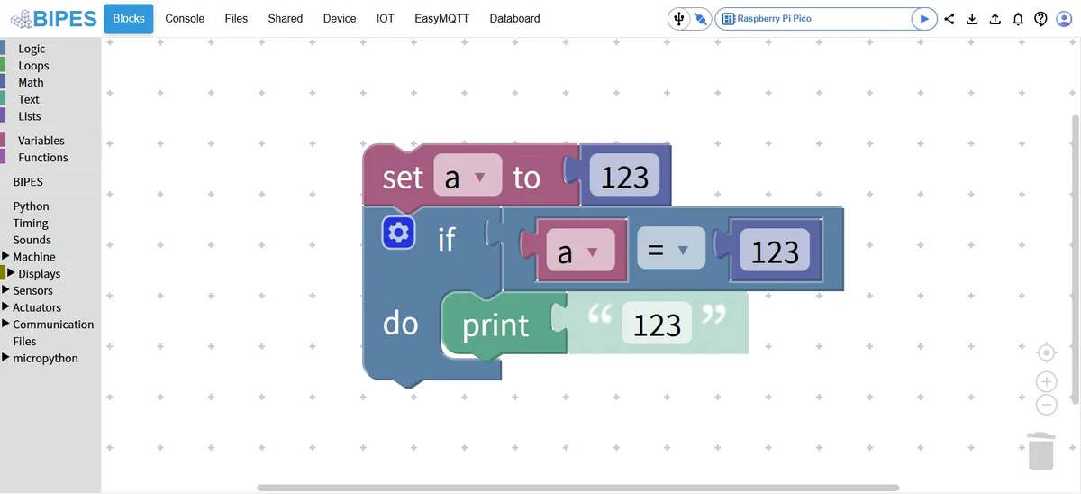
✨ Little Secrets of the Block Area
- Color-coded categories for instant recognition All building blocks are dressed in different colors based on their functions! For example, control blocks are blue, and loop blocks are green. Just like how we sort toys into "building blocks, cars, dolls", these colorful "outfits" help you quickly find the blocks you want without rummaging around.
- Each building block corresponds to a "mini command" and each block maps to a specific action: for example, the "LED on" block means "instruct the LED to light up", while the "read temperature" block means "ask the temperature sensor to report the current temperature". Picking up a block is equivalent to issuing a command to the hardware~
- Drag and drop to use, snap together to make a program Simply drag the desired blocks out of the "toolbox" with your mouse, place them in the "workspace" we’ll introduce later, then snap them together in the order you want — a complete program is ready! It’s as easy as grabbing Lego bricks from a toy box and building a tiny house~
Quick Tips
When building with blocks, pay attention to the "logical order"! For example, if you want to make "the light turns on when the button is pressed", you should first drag the block "when the button is pressed", then drag the block "LED light turns on", and "snap" them together like building Lego (there are small protrusions and grooves on the edges of the blocks that can fit precisely). If you put them in the wrong order, the program will "act up" and won't work as we expect~
3.2 Device Area (Device)
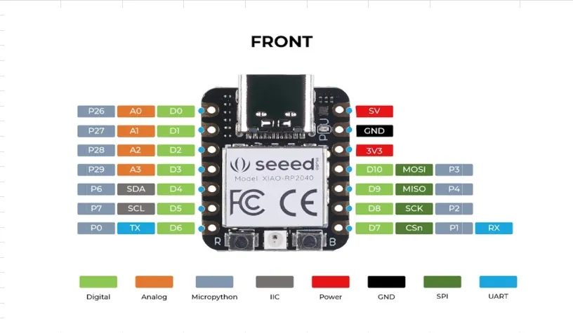
The device area is just like a "body map" of the main control board, which clearly marks the positions and names of all the "golden little hands"(pins) on the main control board! For example, which pin is "GP2", which pin can be connected to an LED light, and which one can be connected to a sensor — all these can be seen at a glance here~
The significant role of the equipment area:
- Help us "find the right place to connect" When we want to connect the LED light to the main control board, first check the map in the device area to find a suitable pin (such as P2), then wire according to the position on the map, and we won't connect it wrong! It's just like when we use the school map to find the restroom or the classroom, we won't get lost~
- Sort out the relationship between programs and hardware For example, when we select the block "control the LED on pin P2 to turn on" in the blocks, then look at the P2 position in the device area, we will understand: "Oh, so this block is instructing the pin at this position to work!", which makes us clearly know how the program controls the hardware~
3.3 Program Execution and Code Area (Console)
This area serves as our "program operation console" and also the "message board" for hardware! Whether the program we've assembled can run and whether there's any feedback from hardware will all be displayed here~ It mainly has two core functions, just like the "start button" and "display screen" of the remote-controlled car we play with!
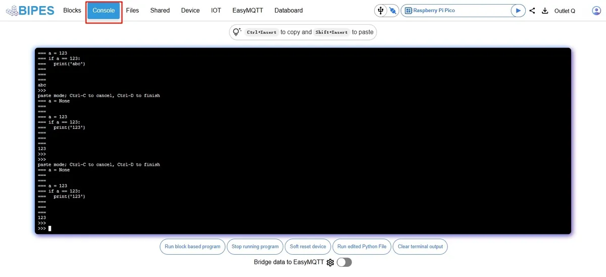
🚀 Core Function 1: Launch the program and check the effect
After we assemble the block program in the workspace, click the "Run" button (usually a green triangle) in this area, and the program will be sent to the Pico main control board, then the hardware will start working according to the instructions! For example, if we assemble the block "LED light on for 2 seconds", after clicking run, we can see the LED light actually turn on, and a corresponding prompt will be displayed here at the same time~
📢 Core Feature 2: Receive "small messages" from hardware
This area also serves as the "message board" for the hardware! If our program contains instructions like "read temperature" and "read brightness", the information perceived by the sensors (such as "25°C now" and "very bright now") will be displayed here; if there is a typo in the program (for example, the building blocks are not connected properly), a "small reminder" will pop up here to tell us "where the error is" and help us modify it quickly~
Super Fun Interactive Mini Class
- Think about it: Why are the building blocks in the block area divided into different colors? (Answer: They are sorted by function, which makes it easier for us to quickly find the blocks we want~)
- Group discussion: If the LED does not light up after clicking the "Run" button, what could be the possible reasons? (Please have the group representative speak. Hint: 1. The blocks are not assembled correctly; 2. The hardware is not connected properly; 3. The "Run" button is not clicked~)
Core Quick Summary
The three core zones each have their own designated roles: the block zone serves as the "magic block box" where we select instructions, the equipment zone acts as the "main control board map" to help us locate wiring positions, and the program execution and code zone functions as the "message board" to assist us in running programs and viewing feedback.
Remember the functions of these three areas, and it will be super easy for us when we do the hands-on operation later!
In the upcoming lessons, we will drag the blocks by hand and click to run, making the hardware really work according to our instructions! Now you can talk to your deskmate about which area's function you most want to try first?