
Contents
1. Introduction
In previous lessons, we have learned to use Serial.print () and Serial.read () to send and receive data between the ESP32 and a computer. This may seem straightforward, but these are only operations at the application layer. As for how data is actually transmitted at the underlying layer, what the data format looks like, and how the ESP32 and the computer ensure that "what is sent can be correctly understood" — these questions actually involve the Serial Communication Protocol.
The Arduino framework encapsulates most of the details for us, so we don’t need to worry about them under normal circumstances. However, when it comes to communicating with peripherals, improving data reliability, or customizing data formats, it is necessary to thoroughly understand the serial port protocol.
2. Complete Process of Serial Communication: From Sender to Receiver
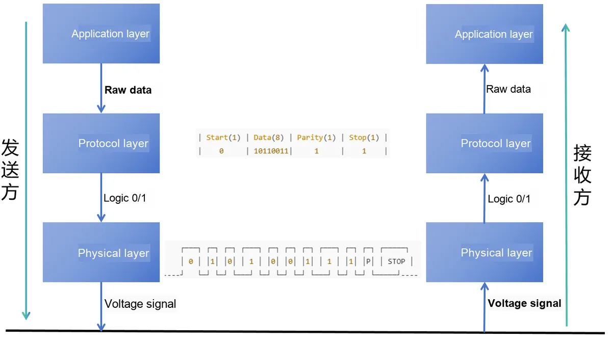
To better understand UART, let's start with a practical example. Suppose a device is to transmit a temperature reading of 179°C, the data will go through three levels of processing:
- Application Layer: What is data?
- Protocol Layer: How to package data?
- Physical Layer: How is data converted into electrical signals for transmission?
The receiving party will carry out the same process in reverse.
2.1 Sender: Send temperature value 179°C
- Application Layer: Determines the content to be transmitted
Devices cannot randomly send 10110011 to each other; just as conversations require grammar, data also needs a unified "format". In UART, this format is data frame (Frame). A typical data frame consists of:
The application layer only cares about "what I need to send". Here is the temperature value 179. Since computers cannot understand the decimal number "179", it needs to be converted into binary:
179 (decimal) → 10110011 (binary)The application layer does not care how the data is measured (e. g., sensor specifics); it only tells the protocol layer: What I need to transmit is 10110011.
Here, the value we intend to transmit is
179— this physical quantity needs to be converted into a binary form processable by machines: the temperature value179in binary is10110011(0xB3). - Protocol Layer: Encapsulate data into a standard format
An individual binary digit string (e. g.
10110011) has no delimiters for the receiver, which has no idea where this data starts or ends, nor can it determine whether the data contains errors. To address this issue, UART introduces the concept of data frame at the protocol layer.The protocol layer does not care about the actual meaning of the data, and it is only responsible for ensuring that the data is correctly encapsulated into data frames in accordance with the protocol specifications.
Simply put, when electronic devices communicate with each other, they need to transmit data in the format specified by the serial port Communication Protocol, otherwise the receiver will not be able to understand it. This fixed format is called a data frame, which is equivalent to a complete "rule for communication".
In UART serial communication, a data frame typically consists of four parts:
- Start bit —— The device initiates communication by signaling "I am starting transmission"
- Data bits —— carry the actual content, for example,
10110011(which is equivalent to179) - Parity Bit (Optional)—— Used to verify whether there are errors in the data, equivalent to asking "Did you get that? "
- Stop bit —— meaning "I'm done transmitting"
Combining these components together yields a complete data frame:
Start bit 0 | Data bits 10110011 | (Optional parity bit) | Stop bit 1 - Physical Layer ("electronic devices transmit electrical signals")
The protocol layer encapsulates data into "data frames", but these are still just abstract 0s and 1s. For two devices to actually communicate, these 0s and 1s must be converted into electrical signals and transmitted over a wire. This is the job of the physical layer.
The physical layer does not care what the data is; it is only responsible for converting the 0s and 1s into actual electrical signals according to the data frames from the protocol layer.
In UART communication, the physical layer adopts electrical level signals to represent logical 0 and 1.
At this stage, the data frames need to be converted into actual voltage signals.
As we mentioned in the previous chapter, "the essence of data transmission between electronic devices is essentially the transmission of electrical signals, which transmits 0s and 1s via voltage signals." For example:
- 0 can be represented by 0V.
- 1 can be represented by 3.3V (or 5V)
Data frame
0 | 10110011 | 1 | 1→ level signal0V | 3.3V-0V-3.3V-3.3V-0V-0V-3.3V-3.3V | 3.3V | 3.3V.To summarize, the physical layer only defines the characteristics of real signals (such as voltage, current, driving capability, etc.) and the correspondence between electrical signals and logical signals 0 and 1.
2.2 Receiver: Receiving temperature value 179°C
After the sender transmits data via the bus, the receiving device will correctly convert these "electrical signals" back into meaningful values in accordance with the protocol rules. This process is exactly the reverse of the sending process.
Physical Layer: The receiver first needs to sense the voltage changes on the bus, and the goal of this step is to ensure that "level changes" can be recognized as stable individual 0s and 1s.
Protocol Layer: The received 0s and 1s are parsed according to the frame format specified in the protocol. For example: parse the data frame 0 | 10110011 | 1 | 1 to extract the original binary data 10110011.
Application Layer: parses 10110011 back into the temperature value 179°C
2.3 Summary
So far, we have walked through the entire basic process of data communication:
- Sender: The temperature data (179°C) is transmitted from the application layer and converted layer by layer downwards → first encapsulated into a protocol frame, then converted into binary, and finally sent onto the bus in the form of electrical level signals.
- Receiver: performs the reverse operation: receives level signals from the physical layer → parses data at the protocol layer → restores the data to "179°C" at the application layer.
It can be seen that essentially, data transmission is a process of encapsulation and decapsulation layer by layer as follows:
- Physical Layer: Ensures the transmission of raw data over physical media, and defines standards for mechanical and electrical characteristics in communication systems (such as voltage levels, transmission rates, and driving capability).
- Protocol Layer: Responsible for unifying communication logic, it specifies the data frame structure, as well as the packaging and unpackaging methods for both transmitting and receiving parties, ensuring that the receiving end can correctly identify the data.
- Application Layer: Oriented to practical requirements, it converts binary data into specific meanings (such as temperature, text, etc.) for use by upper-layer applications.
3. ESP32 UART Peripheral
In our previous studies, we have been using Serial.begin (), Serial.print (), Serial.read () and other such functions for serial communication. The Serial here is actually a software interface provided by the Arduino framework, which essentially calls the internal UART hardware peripheral inside the ESP32 chip.
That is to say:
- Serial is a "software class" that we call when writing code, and it encapsulates the functions for sending and receiving data for us.
- UART is a hardware module inside the ESP32 chip that is actually responsible for converting 0s and 1s into electrical signals, sending them out through pins, or receiving them back from pins.
The ESP32 has a total of three UART ports (UART0, UART1, UART2), each of which is equipped with corresponding TX and RX pins. We connect to external devices through these serial port pins for data transmission.
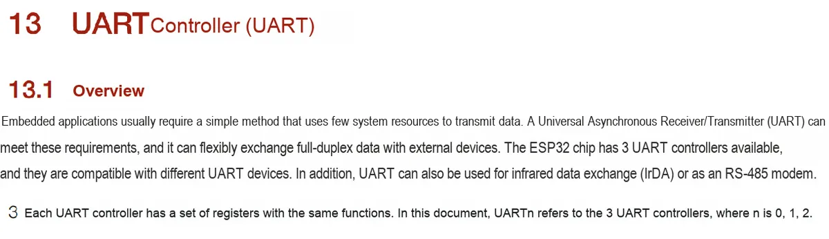
3.1 Physical Layer
The physical layer is the lowest layer of serial communication, which determines the transmission mode of data between devices.
Simply put, the physical layer acts as a "communication channel" between two devices, through which data is transmitted in the form of voltage signals. The physical layer specifies how these voltage signals represent logical "0" and "1", as well as relevant electrical characteristics such as voltage range, current, and driving capability.
3.1.1 UART Interface
UART is a serial, asynchronous, full-duplex communication method:
- Serial: Transmission and reception of data are intelligently carried out bit by bit over respective data lines
- Asynchronous: no clock line
- Full-duplex: enables bidirectional data transmission — UART has at least two data lines
The most basic UART interface consists of two wires:
- TX (Transmit): Send data
- RX (Receive): Receive data
3.1.2 UART Connection
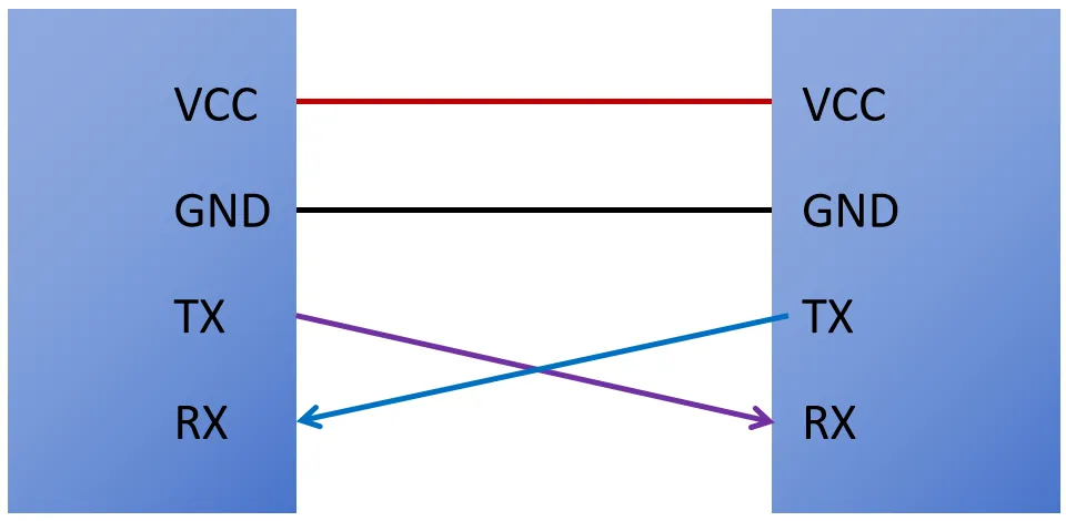
To ensure smooth data transmission between two devices, proper cross-connection is required:
- Connect the TX of the ESP32 to the RX of the peer device
- Connect the RX of the ESP32 to the TX of the counterpart device
This is just like making a phone call: one person's "mouth" should be aligned with the other's "ear", rather than mouth to mouth or ear to ear.
3.3.3 UART Level Standards — Different Physical Layer Implementations
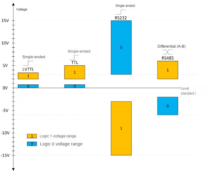
UART data is represented by high and low voltage levels to denote logic 0 and 1. Different devices may follow different level standards, and the common ones are as follows:
- LVTTL (Low Voltage TTL):
- Logic 1:1.2V to 3.3V.
- Logic 0:0 V to 0.4 V.
- Low-voltage TTL logic level, suitable for low-power devices such as modern microcontrollers (e. g. ESP32).
- TTL (Transistor-Transistor Logic):
- Logic 1:2.4V to 5V.
- Logic 0:0V to 0.8V.
- Standard TTL levels are widely used in traditional microcontrollers and embedded systems.
- RS232:
- Logic 1:-3V to -15V (negative voltage).
- Logic 0:+ 3V to + 15V (positive voltage).
- RS232 is a single-ended voltage standard featuring a wide voltage range and strong anti-interference capability, which is commonly used in legacy serial port devices.
- RS485:
- Differential signal: It uses the voltage difference between two wires, A and B, to represent logic states.
- Logic 1: A > B.
- Logic 0: A < B.
- RS485 is suitable for long-distance communication and is commonly used in industrial control and bus communication scenarios.
- Differential signal: It uses the voltage difference between two wires, A and B, to represent logic states.
3.2 Protocol Layer
To ensure that the two communicating parties can exchange data correctly, they must agree on these packet formats. The protocol layer defines the structure of data packets. A standard serial port data packet typically consists of a start bit, data bits, and a parity bit and a stop bit.
In the UART protocol, we can analyze and understand the communication process from two aspects: baud rate and data packet format.
3.2.1 Baud Rate
The principle of serial communication is that both parties agree on a communication rate, and then transmit data one bit at a time.
Baud rate refers to the data transmission rate, usually measured in "bits per second (bps)". For example, a baud rate of 9600 means that 9600 bits can be transmitted per second.
Since serial communication is asynchronous and there is no separate clock line between the two parties, the transmitter and the receiver must use the same baud rate to transmit data correctly.
3.2.2 Data Format
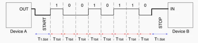
UART data is packaged into data frames in a specific format and transmitted over the physical link in units of frames. Each data frame consists of a start bit, data bits, a parity bit, and a stop bit.
Communication parties must ensure that they use the same data format to guarantee the correct transmission and interpretation of data.


3.2.2.1 Start Bit
In UART asynchronous communication, there is no clock signal serving as a synchronization reference, so the two communicating parties need a "flag" to inform the receiving end that a data frame starts here. This flag is the Start Bit.
- Definition: The start bit is the beginning of each data frame, which is used to notify the receiver that data transmission is about to start.
- Length: fixed at 1 digit.
- Logic value: always logic 0 (low level).
- Required or not Mandatory. Without the start bit, the receiving end cannot identify when the data transmission starts.
- Function: When the bus is in an idle state, the signal line remains at a high level (logic 1). Once the sender needs to transmit data, it pulls the TX line low (logic 0) to form a start bit; after detecting this "low-level transition", the receiver knows that the subsequent data bits are about to arrive.
3.2.2.2 Data Bits
Following the start bit comes the data bits, which form the core part of a UART data frame and are actually used to transmit the binary data required by the user.
- Definition: A data bit is the part of a data frame that is used to transmit actual information.
- Length: typically 5,6, 7, or 8 bits. In modern microcontrollers (including the ESP32), the most common configuration is 8 data bits.
- Transmission sequence: UART communication specifies that the least significant bit (LSB) is transmitted first, followed by the higher bits in sequence. For example, to send
1010 0110, the actual transmission sequence is0110 0101. - Logical value: Each bit of data is represented by a high level (1) or a low level (0).
- Function: The data bits carry the actual information we intend to transmit (such as characters, sensor values, etc.).
3.2.2.3 Parity Bit (Parity)
To ensure the reliability of data transmission, the UART protocol supports the optional use of a parity bit, which acts as an "error detection marker" appended to the end of the data to help the receiver determine whether an error has occurred during data transmission.
- Definition: A parity bit is an optional bit in a data frame that is used to detect transmission errors.
- Location: The parity bit immediately follows the data bits and precedes the stop bits.
- Required or not: Optional. You can select None, Even, or Odd.
- Logic Rules:
- Even Parity: The sender appends a bit to the data so that the total number of
1sin "data bits + parity bit" is an even number. - Odd Parity: The sender appends a bit to the data so that the total number of
1sin "data bits + parity bit" is an odd number. - No Parity (None): No parity bit is added, and the bit stream directly proceeds to the stop bit.
- Even Parity: The sender appends a bit to the data so that the total number of
- Function: The receiver recalculates the number of
1sin the received data and compares it with the check rule. If they do not match, it indicates that an error (such as interference, loss, or bit flip) may have occurred during transmission. - Limitations :
The parity bit can only detect single-bit errors, and is unable to detect cases where multiple bits fail simultaneously. Therefore, in modern communications, parity bits are generally used for simple scenarios, while more complex systems will combine them with more powerful error detection mechanisms such as CRC and checksums.
Next, let’s look at two examples:
- Example 1: Data bits = 01000001
- There are two 1s in the data bits (an even number).
- Even Parity: Parity bit = 0 (keeps the total number of 1s even) → the data frame remains unchanged.
- Odd Parity: Parity bit = 1 (to make the total number of 1s an odd number).
- Example 2: Data bits = 01010101
- There are four 1s (an even number) in the data bits.
- Even parity: Parity bit = 0 (the total number remains even).
- Odd parity: Parity bit = 1 (to make the total number of 1s an odd number).
3.2.2.4 Stop Bits
In UART communication, the stop bit is used to mark the end of a data frame, enabling the receiver to confirm whether the data has been completely transmitted and prepare for the next frame of communication.
- Definition: A stop bit serves as the end marker of a data frame, which is used to notify the receiver that the transmission of this frame of data has been completed.
- Length: can be 1 digit, 1.5 digits or 2 digits (1 digit is commonly used).
- Logic value: Always logic 1 (high level).
- Required or not: Mandatory; if absent, the receiver will be unable to determine when the data ends.
- Function: The stop bit helps the receiver distinguish between different data frames and ensures the stability and synchronization of the communication process.
3.2.2.5 Idle State Bit
In UART communication, after the transmission of a data frame is completed, the communication line will remain at a high level (logic 1), and this state is called an idle bit.
- Definition: An idle bit refers to the line state after data transmission is completed, which is used to indicate that the bus is in an idle state.
- Logic value: Logic 1 (high level).
- Required or not Must be present to ensure stable communication.
- Function: The idle bit provides the receiver with a time window to identify the start of the next frame of data, maintains the continuity and stability of data transmission, and facilitates synchronous asynchronous communication at the same time.
4. Transmission Example
The two parties stipulate in advance that the data format of 8 data bits, no parity and 1 stop bit shall be used for transmission.
When transmitting the character '1', '1' -> 00110001 (8-bit binary)
In ASCII encoding, the character '1' is represented in binary as 0011 0001 (transmitted from the least significant bit to the most significant bit). The content of each frame is as follows:
- Start bit: 1 bit, logic 0.
- Data bits: 8 bits, which are in sequence: 1 (LSB), 0,0, 0,0, 1,1, 0 (MSB).
- Parity bit: None.
- Stop bit: 1 bit, logic 1.
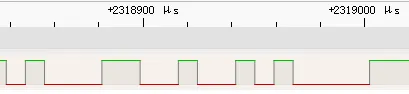
The corresponding waveform analysis is as follows:
- Start bit: Low level (logic 0).
- Data bit:
- Bit 1: High level (logic 1).
- Bit 2: Low level (logic 0).
- 3rd bit: Low level (logic 0).
- 4th bit: Low level (logic 0).
- 5th bit: Low level (logic 0).
- Bit 6: High level (logic 1).
- Bit 7: High level (logic 1).
- 8th bit: Low level (logic 0).
- Stop bit: High level (logic 1).
5. Summary of This Chapter
This chapter introduces the UART serial communication of the ESP32 and its underlying principles. From the underlying perspective, UART communication can be divided into three layers: the physical layer, the protocol layer and the application layer.
The physical layer is responsible for transmitting data via level signals between TX/RX pins. Different standards (such as LVTTL, TTL, RS232, and RS485) specify voltage ranges and signal characteristics. It only focuses on how signals are transmitted, without concerning itself with the actual meaning of the data.
Before data transmission, the protocol layer encapsulates data into frames consisting of a start bit, data bits, an optional parity bit, and a stop bit. This ensures that both the transmitter and the receiver can identify data boundaries in accordance with unified rules and perform basic error detection. Baud rate, data bit length, parity mode, and the number of stop bits are all key parameters specified by the protocol layer.
The application layer processes actual data, converts specific information such as temperature, characters or sensor values into binary for transmission, or restores the received binary data to its specific meaning, providing usable information for upper-layer applications.
UART data transmission is essentially a process of layered encapsulation and decapsulation: the application layer focuses on content, the protocol layer standardizes the format, and the physical layer completes signal transmission. Understanding this process is the foundation for communicating with peripherals, improving reliability, and customizing data formats. Through a specific example (such as transmitting the character '1'), we can see how data is encapsulated into a data frame, transmitted via level changes at the physical layer, and correctly parsed by the receiver.
Understanding the UART Communication Protocol allows us to clearly grasp how data is transmitted from the ESP32 and how the receiving end processes it, which helps avoid errors when connecting sensors, modules or external devices, and also facilitates us to design data formats that meet actual needs.
6. Reference Links
https://dreamsourcelab.cn/logic-analyzer/uart/
https://doc.embedfire.com/mcu/stm32/f103/hal_generalzh/latest/doc/chapter20/chapter20.html
https://wiki-power.com/%E9%80%9A%E4%BF%A1%E5%8D%8F%E8%AE%AE-%E4%B8%B2%E5%8F%A3%E9%80%9A%E4%BF%A1/#_6
https://openatomworkshop.csdn.net/674000c72db35d11950fb43b.html?dp_token=eyJ0eXAiOiJKV1QiLCJhbGciOiJIUzI1NiJ9.eyJpZCI6Nzg5MjYxMiwiZXhwIjoxNzM2NzM3MTgyLCJpYXQiOjE3MzYxMzIzODIsInVzZXJuYW1lIjoicXFfNjI4NDY5MjAifQ.PMYoxXMJNWVLDw08DOtWFpA9ne3LTmDrNGe9kq73Hww&spm=1001.2101.3001.6661.1&utm_medium=distribute.pc_relevant_t0.none-task-blog-2%7Edefault%7EBlogCommendFromBaidu%7Eactivity-1-140592436-blog-136001074.235%5Ev43%5Epc_blog_bottom_relevance_base4&depth_1-utm_source=distribute.pc_relevant_t0.none-task-blog-2%7Edefault%7EBlogCommendFromBaidu%7Eactivity-1-140592436-blog-136001074.235%5Ev43%5Epc_blog_bottom_relevance_base4&utm_relevant_index=1