
You have a sensor reading on a small screen, and the same value is reaching a phone. For a team developing an outdoor accessory or an environmental teaching kit, that is a real milestone: sensing, display and wireless link have started to work together. The next question is what you can responsibly tell someone about that number.
We built a bench version with a GUVA-S12SD UV sensor module, an HC-08 Bluetooth module and an OLED on a GraftPort RP2040 board running MicroPython 1.23, in an acrylic enclosure. Below we follow the data path we demonstrated and separate it from the measurement checks a finished product would need.
Start with the decision your user needs to make
For an educational prototype, the goal might be to show that the sensor responds and to explain how its value travels to the phone. A device meant to report outdoor UV exposure has a bigger job: sensor response, placement, enclosure, interpretation and missing data all affect the result. Those are different levels of validation even when the electronics look the same.
A recent All About Circuits design-contest entry proposed an environmental wristband with local readings, Bluetooth and offline history, and listed future checks of orientation, clothing, reconnection and record integrity. It is one proposal on a different platform, not a completed wearable, but its test list is the right shape.
For our build, the narrower question is: can we get a repeatable sensor response, show it locally, and explain exactly what is transmitted?
Connect the sensor, radio and screen separately
The UV module goes to ADC0, the HC-08 to UART0 and the OLED to I2C0. Keeping those paths separate makes it easier to tell whether a problem is in sensing, display or communication.
UART0 runs at 9600 baud. That is the link between controller and radio module, not the phone's end-to-end update rate; match the module's actual configuration before treating a missing packet as a sensor fault. The OLED scan accepts 0x3C or 0x3D, so confirm your module's address and pin mapping rather than copying a connector label from another board.
The battery cable we used is labeled red for ground and black for supply, the reverse of the usual expectation. Follow the connector polarity, not wire color. On this board, RUN switch 2 must be on when no external watchdog module is fitted.
Build the enclosure without forgetting the optical path
The boards are fixed to a base with M3 hardware under acrylic panels. Leave access to the sensor and its wiring so you can compare readings before and after closing the enclosure.
A cover that looks clear to you has not been qualified for the sensor's wavelength range. The sensor maker's application note discusses optical response and window materials across its packages. For a product, get transmission data for the actual cover and compare measurements with and without it under controlled conditions. We did not test our acrylic's UV transmission, and nothing here establishes weather resistance or battery life.
Follow the conversion before calling it a UV Index
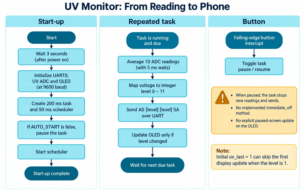
The UV driver averages ten ADC readings with a 5 ms wait after each, converts the average using a 3.3 V reference assumption, and looks the voltage up in an empirical table that returns an integer from 0 to 11. Below 227 mV it returns 0; from 227 mV up to 318 mV it returns 1; at 1170 mV and above it returns 11. The top value is a software cap, not proof that the input stopped rising.
We do not have the calibration data that would show these levels reproduce a reference UV Index across the conditions you care about. Treat the number as the prototype's estimated level until you have validated it with the actual module and optical arrangement.
Even the test light has to match the sensor. Adafruit's page for its GUVA-S12SD breakout gives a 240 to 370 nm response range and notes that its 400 nm LEDs fall outside it. Adafruit's amplifier and conversion are not necessarily the same as our module's, but the point carries: a bright-looking lamp is not a reference. In our bench recording, a handheld light near the sensor still showed level 0, which says nothing about a calibrated response.
Make the transmitted value easy to inspect
The task runs on a 200 ms interval with a 50 ms scheduler tick. The ten sampling waits and the other work add time, so those are configuration values, not a latency measurement.
Each pass sends a four-byte packet:
A5 <level> <level> 5A
The two middle bytes repeat the same level, so A5 03 03 5A is level 3 and A5 0B 0B 5A is level 11. There is no timestamp, sequence number or acknowledgment. Repeating the value does not record when it was measured or prove every reading arrived.
The OLED updates only when the level changes, while a packet goes out on every pass. Keep that distinction in mind when testing: an unchanged screen does not mean transmission stopped. There is also a startup edge case. The previous level starts at 1, so a first reading of 1 can skip the first display update; an explicit first-update flag would fix it.
Our phone debug log shows packets for levels 0, 11 and 3. The same screen's header also reads "device not connected" with a receive rate of zero, so it is retained data from earlier, not proof of a live connection at the moment it was captured. Read debug screens for their connection state as well as their data.
Test interruptions and pauses
For the next test, record the local reading and the received packet together while changing the input in a controlled way. Then disconnect and reconnect the phone. Decide whether the interface should show the last reading, a stale-data label or no value, and make that visible. Our firmware stores no history and does not recover missed readings.
Test the pause button too. Our handler pauses or resumes the task but also tries to call a method this task class does not implement, and the error is suppressed. Nothing updates the screen to say it is paused, so the old value stays up. A visible paused state and an indication of data age are the next useful changes; a frozen number should never look like current conditions.
Choose the next validation step
For a teaching kit, the most useful improvement may be a clear explanation of the estimated level, the packet format and the connection state. For an outdoor accessory, add a documented comparison with a suitable reference instrument, test the actual cover and sensor orientation, and define what the phone shows during interruptions. Our build has not established personal-exposure accuracy, weatherproofing or wearable performance.