
If you are building a small wheeled prototype, getting a motor to turn is an encouraging first result. The next question is what happens when someone releases the control. Does the wheel slow down gently, roll too far, or stop abruptly enough to jolt the mechanism?
That choice shapes how the prototype feels. In a 2017 Arduino discussion, a builder with a skid-steer robot wanted something between free coasting and a harsh stop. The concern was the gears, not whether the code could switch the motor off. It is worth settling before a moving prototype goes into someone else's hands.
On our bench we drove one motor and wheel from a GraftPort-RP2040 controller board through a GraftSense I2C DC motor driver, ran it for ten seconds and stopped it. Then we looked at what the stop command actually does. This is a bench demonstration; choosing a stopping behavior for a complete robot needs a further test with the real mechanism.
Separate the command from the power that moves the wheel
The controller sends instructions over I2C, a two-wire bus. On this module a PCA9685 turns them into PWM signals, repeated on/off pulses with adjustable on-time, and SS6285L bridge drivers switch the motor power. That is why the small communication connector and the motor supply have different jobs.
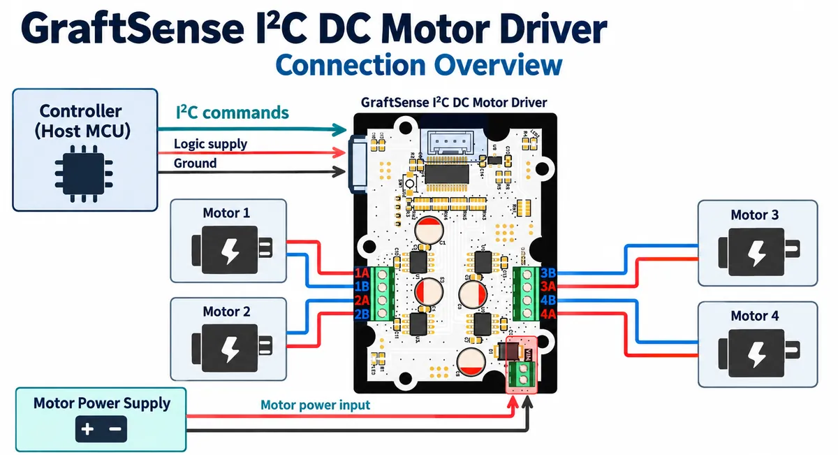
The module has four motor channels, each with two outputs so the driver can reverse the voltage across the motor. Two wheels could later use two channels, but steering and matching their speeds are separate tasks.
The motor supply must suit the motor as well as the driver. We used an LM2596S adjustable supply module set to 7.4 V. That is our setup, not a default for every small motor. Check your motor's voltage and current requirements and the supply's ability to handle starting current.
The module also has a button that disables PWM output while held. Treat it as a bench control and check its behavior in your setup. It is not a complete emergency-stop system, and disabling drive does not necessarily stop a wheel immediately.
The single-motor experiment
A four-wire cable connects the controller to the module. The code uses I2C0 with GP4 as SDA and GP5 as SCL, at 400 kHz. The external supply goes to the motor-power input, and the motor's two wires go to terminals 4A and 4B. Confirm labels and polarity on your actual board before powering it.
Address-selection pads on the back let the module share a bus with other devices; our scan found it at 0x42. Record your own board's address rather than assuming that value. Our test program scanned for any device in 0x40 to 0x4F before creating the driver object. For a repeatable setup, select the expected address explicitly and stop initialization if it is missing; a device answering in that range is not proof that you found the motor board. Start with the wheel off the bench surface so an unexpected command cannot send the prototype moving.
The active part of the test was short: command motor 4 with a PWM value of 4000 in direction 0, wait ten seconds, then call the driver's stop method. The 4000 is a PWM command, not 4,000 revolutions per minute, and which way the wheel turns also depends on the motor wiring and mounting. There was no encoder, so nothing measured or regulated speed.
Two details of the driver are not obvious from its method names. It accepts speed commands from 1900 to 4095, and at construction it sets all eight control outputs high, which is the bridge's brake state. Record the driver version with your test notes.
The console showed the scan, the start message, writes to PWM channels 6 and 7, and the stop message, and the motor followed the programmed sequence. There is no measured wheel speed or stopping distance in that record. What it establishes is the basic chain: the board can address the module and issue a run and stop sequence to the connected motor.
Before relying on repeated runs, check the driver's PCA9685 setup routines against the NXP PCA9685 datasheet, sections 7.3.1, 7.3.2 and 7.3.5. The prescaler formula ends with a minus one, and after an oscillator restart the internal oscillator needs 500 microseconds to stabilize. A clean console transcript does not settle startup timing.
"Stop" and "brake" are different output states
For the SS6285L, two low control inputs leave the motor outputs open (high impedance). The driver stops pushing current and the motor coasts as friction and load slow it. Two high inputs pull both outputs low, which brakes the motor electrically.
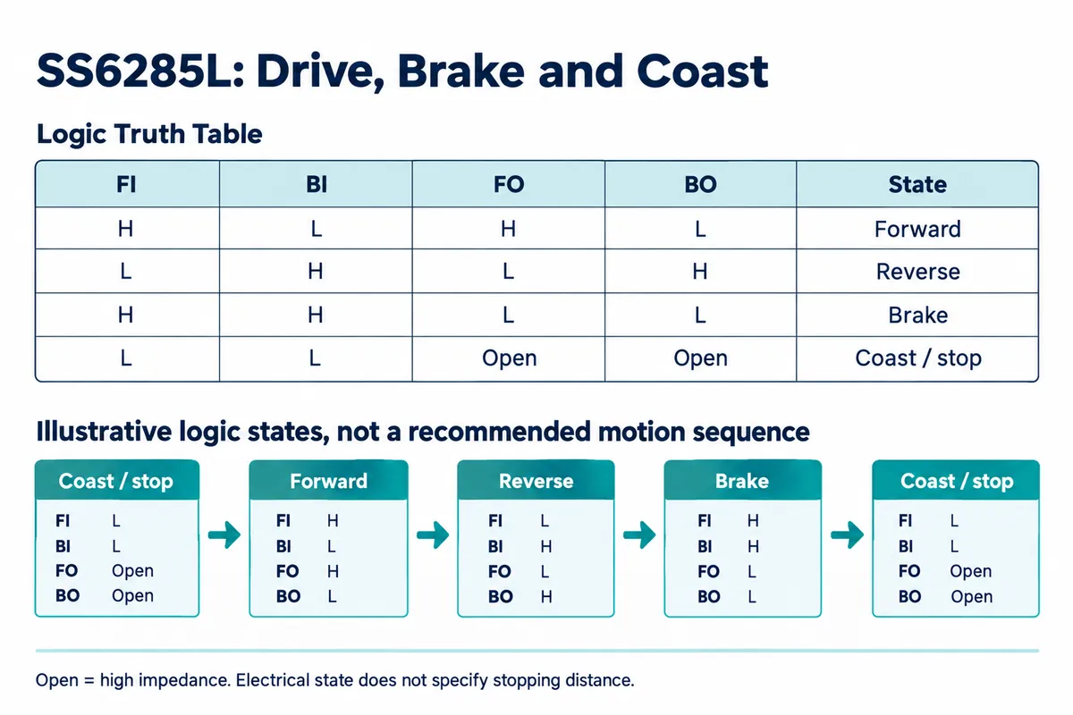
In the driver we used, the stop method sets both control outputs low, so the wheel coasts; a separate brake method sets both high. Check how your driver handles stop versus brake before relying on it. Our test called only the stop method and did not compare the two on a moving chassis.
Pololu's brake and coast explanation describes the same distinction for other controllers. The input truth tables are device-specific, so do not carry another board's pin states over to this one. Reversing direction deserves the same attention: test deceleration and reversal on purpose rather than assuming a direction flag makes the mechanical transition gentle.
Turn the bench result into a useful product test
Once the basic run is repeatable, put the question back into the intended setting. For a small classroom robot, that might mean stopping before the edge of a marked area; for a moving exhibit, avoiding a visible jerk. Write down the desired behavior, then compare coasting and braking at a modest speed with the real wheel, load and surface.
Record the command, supply voltage, load, time to stop and distance traveled, in both directions. If results change as the battery drops or the mechanism warms, that helps decide whether open-loop commands are enough or whether you need speed feedback and a more deliberate motion controller.
Do not size a product from a "5 A" figure alone. That is a driver-chip rating under specified conditions; the module's connectors, copper, cooling, supply and simultaneous motor loads also matter. Establish the running and starting current you need, then check the assembled board at that load before committing to an enclosure or a batch.
Finally, check what happens when the program is interrupted or communication is lost. The PCA9685 keeps generating pulses on its own, so stopping Python does not necessarily clear the last motor command. Define the required fault behavior and verify it as a separate test before a user trial. The milestone is a prototype that starts, stops and changes direction in a way someone can predict.