
A display or control interface runs through its demo without a problem. Then you add the rest of the application, and it occasionally pauses between updates. The next message behaves differently, even though the chosen clock speed has not changed. Before trying a faster processor, check what the interface does while it waits for data.
For a team integrating a custom display, a clocked output module or a test fixture, the quiet interval is part of the interaction between devices. The receiver sees the clock level, data level and any selection signals throughout that interval. An output sequence that is correct while running can still have an unsuitable pause or restart behavior.
A small RP2040 PIO example makes this visible. It sends four data bits, then fetches another word. The interesting detail is where it waits when no word is available: the outgoing clock stays high. That is a property of this program, not a rule every PIO interface should follow.
Separate the clock you send from the clock running the processor
PIO is a small hardware sequencer that executes pin operations alongside the main application. In this example, one pin carries data and a second carries a clock for the receiving device. PIO's side-set feature changes that clock pin as part of an instruction. That outgoing clock is different from the internal clock that advances the sequencer.
The program uses a transmit FIFO: a short queue of words supplied by software or by another data-transfer mechanism. A PULL instruction takes the next word into PIO's output shift register, where later instructions send its bits. If a blocking pull has no word to take, the program waits there.
Here is the manual-pull example from the RP2040 datasheet, section 3.5.4, which documents it and its timing. It is PIO assembly, not a complete MicroPython application; pin mapping, shift direction and other setup still have to come from the surrounding program.
.program manual_pull
.side_set 1 opt
.wrap_target
    set x, 2
    pull side 1 [1]
bitloop:
    out pins, 1 side 0 [1]
    jmp x-- bitloop side 1 [1]
    out pins, 1 side 0
.wrap
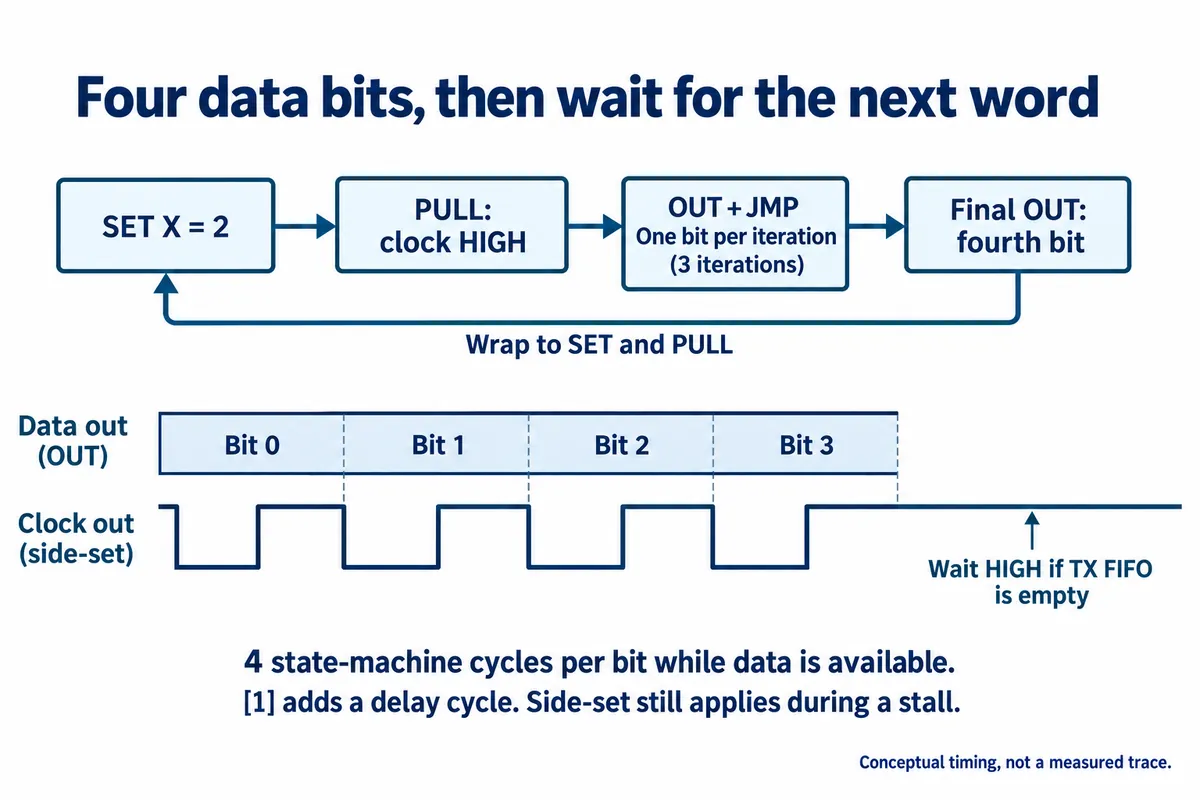
The repeated OUT and JMP sequence sends three bits. The final OUT sends the fourth, then execution wraps to the beginning. With data available, the sequence keeps four state-machine cycles per bit. The [1] notation adds a delay cycle, so it is wrong to say every instruction here takes exactly one clock. The timing sketch is conceptual, not a logic-analyzer capture.
Waiting does not cancel the pin operation
The decisive instruction is pull side 1 [1]. When it has to wait for the next word, its side-set action still takes effect. The outgoing clock therefore remains high during that wait. The rest of the program is stalled, but "stalled" does not mean every part of the instruction has been postponed.
This has confused developers reading the hardware documentation. In a June 7, 2022 Raspberry Pi documentation issue, an emulator author asked about the precise conditions under which automatic loading stalls an output instruction. That report concerns interpreting instruction timing, not a demonstrated fault in this example. It is a good reason to describe the particular instruction and queue state rather than reporting only "PIO stopped."
For your device, ask whether the receiver permits that clock level and an extended gap at that point. Check its timing specification and the surrounding selection or enable signals. Some interfaces can wait; others impose constraints that need a different transfer arrangement. This example has no chip-select control and should not be treated as a complete driver for an arbitrary SPI peripheral.
A shorter program can change the pause
Automatic pulling lets the hardware refill the output register after a configured number of bits have been shifted out. The datasheet compares the manual program with a shorter loop that outputs data with side-set low, then raises the clock in the next instruction. With its written delays it keeps the same bit cadence, but it waits with the clock low when it needs data and cannot get it.
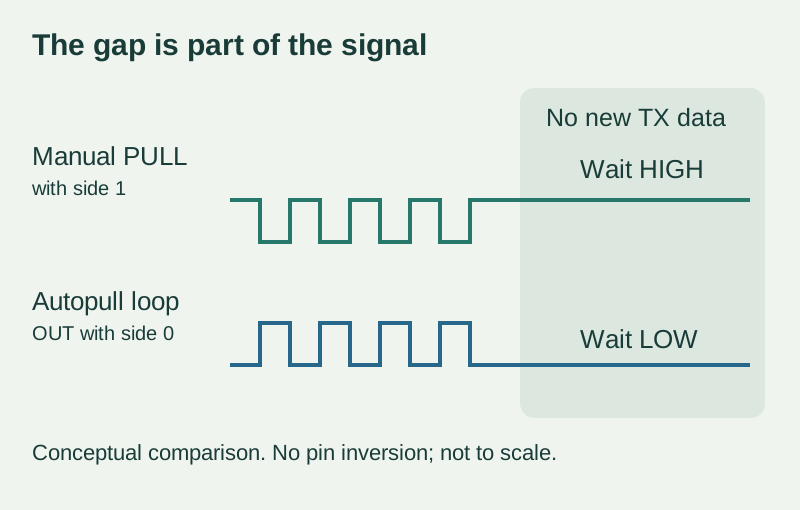
That is the change to discuss during a rewrite: both versions can look right in the middle of a continuous transfer while behaving differently at a gap. Do not assume that removing instructions preserves all externally visible behavior. The shorter loop runs faster only if its delay cycles are also removed. The shaded gap in the sketch is illustrative, not a measured duration, and pin inversion is left out.
The official PIO SPI example deliberately comments on its chosen stall point and clock state, and configures clock polarity separately. Use an appropriate complete implementation and the receiver's requirements to decide what belongs in your product.
Include a deliberate gap in the next integration test
Send a known short pattern, let the data queue empty, then supply the next pattern. Observe the clock, data and any chip-select or enable signal at the receiving end. Record the last bit before the gap, the waiting level and the first bit after it. A logic-analyzer capture spanning that boundary is more useful than a screenshot of the steady stream.
Repeat the check while the application does the work that normally delays it, such as updating its screen or handling a request. Compare the observed gap with the receiver's permitted timing. If the interface requires uninterrupted data, find out how that requirement is guaranteed across the whole transfer. A larger queue can postpone an interruption without removing its cause.
These are proposed tests; we have no capture of this program waiting under application load to report. Keep that distinction in the review so a convincing diagram does not become evidence of a test nobody ran.
The useful outcome is a small, agreed interface contract: which state is held between messages, what the receiver permits, and how the next transfer begins. That gives the team something concrete to preserve when optimizing the firmware or combining features.