
You plug a prototype into a laptop, a new COM port appears, and the power light comes on. That feels like success, until your test tool receives nothing. If you are preparing a few units for colleagues or early users, you need a way to tell whether the problem is the laptop connection, the wiring or the firmware.
A simple USB-to-UART connection can be that service route. It lets a computer read diagnostic messages or send small commands without a finished app. The useful milestone is a message that travels in each direction and is recognized at the other end. A port name alone does not establish that.
On our bench we set this up with a GraftSense CH340K USB-to-TTL module, an RP2040 controller, a short message-sending program and a desktop serial tool. The wiring and recording are worth reusing; a few details needed correcting before it became a repeatable procedure.
Treat recognition and communication as separate steps
The CH340K bridges the laptop's USB connection and the microcontroller's UART, a simple transmit/receive interface. The operating system can recognize the bridge even when the microcontroller sends nothing useful. It is like finding a telephone number: it does not mean anyone answered.
A September 2026 first-PCB discussion shows the distinction. The author reported a port that appeared and disappeared with the board while firmware upload still failed. That was an ESP32 design with its own open questions, but the transferable question is the same: which part of the route has actually been verified?
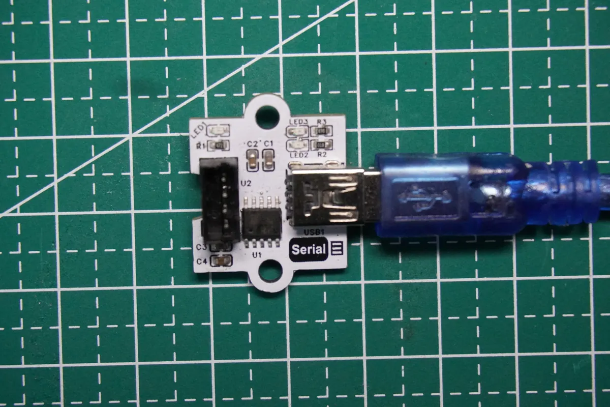
Identify the port by watching which device appears when this adapter is connected. If the controller has its own USB console connection, keep the two port identities distinct. If a driver is needed, use the operating system's supported route or the official WCH driver page, and record the laptop OS, adapter identity and driver version with each test result.
Read the connector labels from the correct side
UART wiring normally connects one device's transmitter to the other's receiver. This carrier labels its connector from the microcontroller's point of view: MTX goes to the bridge's receive input, and MRX comes from the bridge's transmit output. Applying a generic "cross TX and RX" rule a second time would undo the intended mapping.
Our wiring put GP8 on MTX and GP9 on MRX, plus ground and the board's power connection. Check the actual carrier and target supply arrangement before reproducing it. USB's 5 V supply is not, by itself, a specification for the voltage a target UART input can accept.
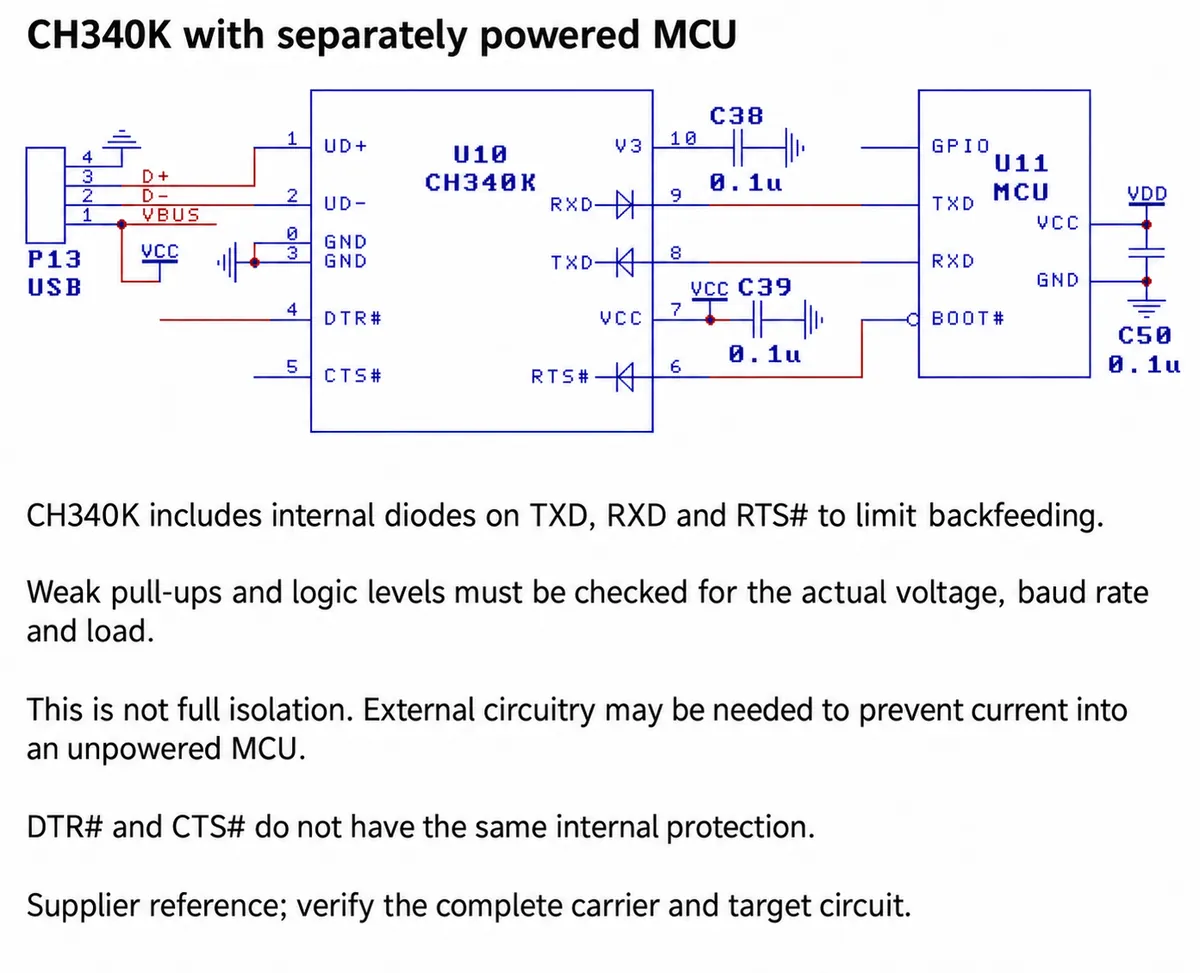
Power state matters too. The CH340K has internal features that limit some backfeed paths when the target is powered separately, but that does not make every combination of board, voltage and unpowered target safe. On this carrier the chip supply is tied to USB 5 V, so check the complete target connection and signal levels.
Correct the UART selection, then send something recognizable
Our first program said it used GP8 and GP9 but created UART(0, ...). On the RP2040 those pins belong to UART1, as the MicroPython 1.23 RP2 reference documents. A connector name on a carrier and the hardware UART number are separate things; code has to use the chip's real mapping.
After verifying the wiring, this small diagnostic sketch uses the right UART, sends numbered lines and shows incoming bytes without assuming they form complete text. It is what we would run next; we have not yet run this revised version on the hardware.
from machine import UART, Pin
import time

uart = UART(1, baudrate=9600, bits=8, parity=None,
            stop=1, tx=Pin(8), rx=Pin(9))
count = 1
next_send = time.ticks_ms()

while True:
    if time.ticks_diff(time.ticks_ms(), next_send) >= 0:
        uart.write("Device message {}\r\n".format(count))
        count += 1
        next_send = time.ticks_add(time.ticks_ms(), 2000)
    incoming = uart.read()
    if incoming:
        print("UART received:", repr(incoming))
    time.sleep_ms(10)
Set the computer's serial tool to 9600 baud, 8 data bits, no parity, 1 stop bit, and no hardware flow control for this two-wire setup. Look for advancing message numbers in that tool. Then send a distinctive short string from the computer and look for it in the controller's console.
Those two observations prove different directions. print() writes to the board's configured console; uart.write() sends bytes through the chosen UART. On a standard MicroPython RP2 setup, the UART is not automatically the interactive console. Keeping the two windows separate makes a missing message easier to locate.
What our recording does and does not show
The desktop recording showed numbered messages arriving in the computer's serial tool. The controller console also showed a received test usb-ttl message, among many "No data" reports. That supports an exchange in both directions, at least at those moments. It does not show uninterrupted communication or an automatic echo of every message.
Our first loop sent a message, waited 100 ms, checked for received bytes and then slept for two seconds. If nobody has sent anything back, "No data" is expected and is not evidence of a broken link. The revised sketch checks for input more often, but it is still a diagnostic, not a production protocol.
For the next test, give each direction its own recognizable message. First confirm the laptop receives the device's counter. Then send a short command from the laptop and confirm the controller reports its bytes. If you need a true round trip, implement a reply explicitly and compare it with what was sent; the USB adapter does not create that behavior on its own.
Give the next person a repeatable service procedure
Before the electronics go inside an enclosure, decide how someone will reach this connection: a service opening, a removable panel or an internal connector. Our bench arrangement is not an access solution. Account for the real cable size, plug orientation and strain on the board.
For a small trial batch, hand over one short procedure:
- Identify the adapter's port.
- Apply the agreed terminal settings.
- Recognize the startup message, including the firmware version.
- Send the test command and save the response.
That turns "it does not work" into a report you can investigate.
Also record what happens when the USB cable is removed, the target is powered separately and the connection is restored. Those observations can reveal a different problem from a transmit/receive wiring error. We have not run that reconnect sequence yet.
Finally, a working diagnostic port is not automatic firmware download. Our four-wire carrier connection does not expose a complete reset and boot-control arrangement. Reference diagrams for other CH340 variants show those extra functions, but this module has not demonstrated them.