
An interactive object that reacts when a hand approaches sounds simple: measure the distance, choose a threshold and turn something on. The hard part is making sure the sensor responds to that hand, from the positions people actually use, rather than to the table, a sleeve or part of its own enclosure.
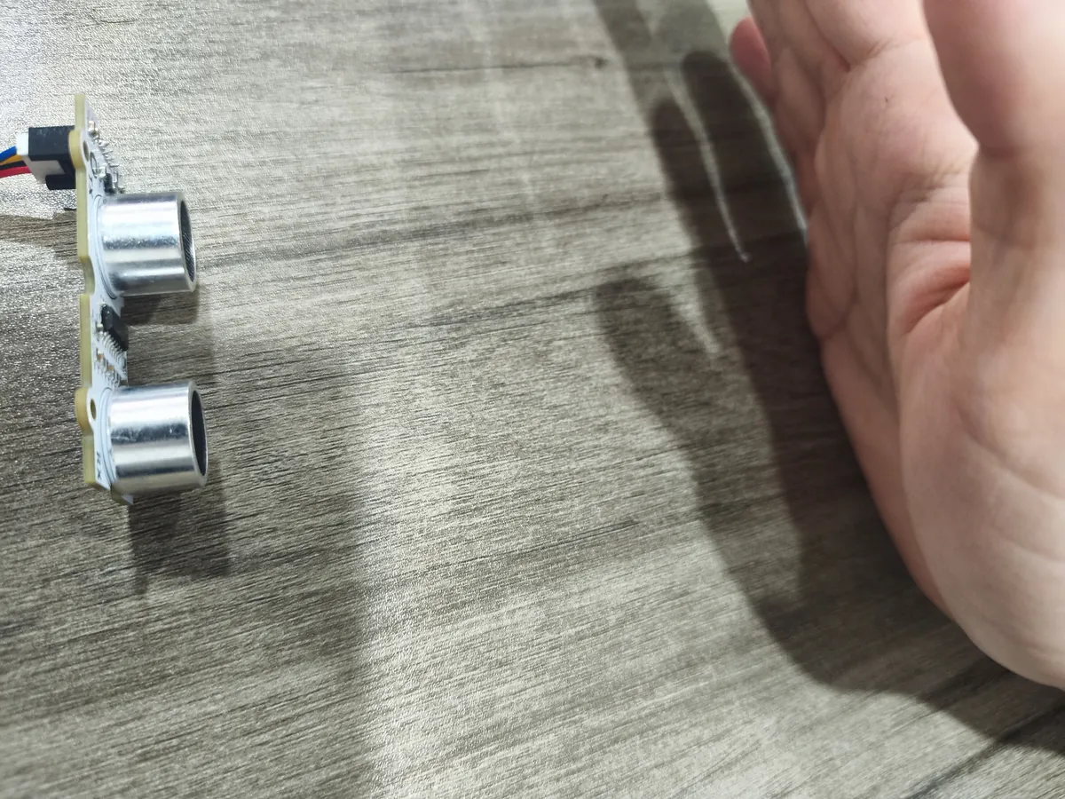
On our bench we connected an RCWL-9620 ultrasonic module on a GraftSense carrier to a Raspberry Pi Pico running MicroPython, read it over I2C and moved a hand in front of the two transducers while the distance values changed. That is enough to explore the next integration questions. It is not a finished gesture detector or a calibrated range test.
Define the target before choosing a distance
"Detect something nearby" leaves decisions open. Is the target a bare hand, a clothed person or a rigid object? Does it approach head-on or from the side? How close must it get, and what should happen when there is no trustworthy reading?
A Reddit AskEngineers discussion about sensing the distance of mixed objects shows why those details matter. The author wants to detect metal, glass and plastic without contact, then stop a moving platform with only a few centimeters of clearance. That is far more demanding than printing distances on a terminal, and our test says nothing about a safe stopping system.
For a first non-safety-critical prototype, pick one narrow behavior: for example, change a light when a hand enters a defined zone in front of a tabletop object. That gives you a specific target, position and response to test.
Follow the sound path
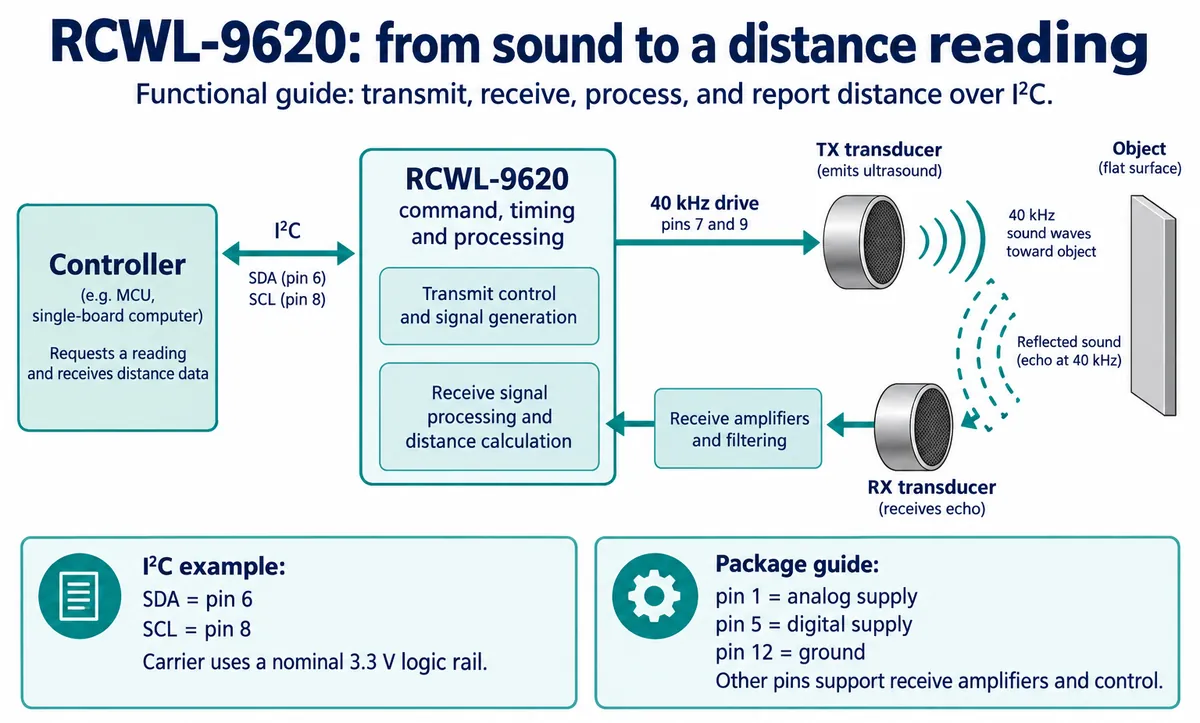
The module has separate transmitting and receiving transducers. The transmitter sends ultrasound toward the target, the receiver picks up the returning sound, and the chip processes it and reports a distance. Over I2C, the application reads a number rather than timing an echo pulse.
The returning sound depends on more than distance. A large, hard surface facing the sensor is a different target from a sleeve, a narrow edge or an angled panel. MaxBotix's guide to reading ultrasonic beam patterns explains how target size and acoustic properties affect detection; its measured patterns belong to its own sensors, not this module.
That matters for the product's front face. The sensor needs a clear acoustic path, and nearby edges can become unintended targets. Start with the transducer faces unobstructed, then test the proposed mounting and surrounding surfaces. A neat pair of holes is a mechanical arrangement to evaluate, not proof that detection stays the same.
The connection and the reading
We used the Pico carrier's I2C0 connector: GP4 for SDA, GP5 for SCL, with power and ground on the same cable, at 100 kHz. The module answered at the 7-bit address 0x57. The carrier feeds a 3.3 V regulator from its 5 V input and pulls SDA and SCL up to 3.3 V. If you move to another board, check connector pin order, supply and pull-up voltage against the actual revision instead of trusting that the cable fits.
The MicroPython driver we used (it credits DFRobot and is MIT-licensed) sends command 0x01, waits 120 ms and reads three bytes, which form a big-endian value divided by 1000 to give millimeters. The chip reference requires a wait of at least 100 ms. Our test loop then printed the value and slept one second, so each reading took at least about 1.12 seconds plus communication and printing time. That is fine for a terminal demo; a product that must react to a quick hand movement needs different timing.
Read the result without giving it more meaning than it has
The terminal found 0x57 and printed values including 246.01 mm, 289.82 mm, 52.57 mm and 29.66 mm as the hand moved. With the photo, that documents a working connection and changing values. With no ruler measurement or error table, it says nothing about how close those values are to the real distance.
The two decimal places come from the print format. Printing hundredths of a millimeter does not demonstrate that accuracy. The range and accuracy figures in the chip reference are manufacturer specifications under stated conditions, measured against a flat wall, not results from our test.
There is also a software limit to catch before adding a trigger. The driver returned min(raw_mm, 4500), so any larger decoded value became 4500 mm, and it did not separately flag a missing echo or an invalid result. A run of maximum values needs investigating; it should not automatically mean "the path is clear."
Give the application a separate "no trustworthy reading" state. During development, keep the unmodified reading and the communication status so you can understand failures. Choose the final validation rules only after checking how the module behaves with no target, with targets outside the useful range and with the actual objects the product should detect.
Make the mount easy to change
Before committing to an enclosure, compare the exposed module with a simple mock-up of the front panel. Move the same target through the intended zone, change its angle, then repeat with the real material or clothing. Record missed detections and unwanted triggers as well as good readings. That tells you whether a software threshold is solving the right problem.
A Reddit post about a repositionable frame for ultrasonic modules shows the value of keeping that adjustment available. It uses a different sensor, the JSN-SR04T, and lets modules move without permanent fasteners.
If readings jump when the target moves slightly, look at the geometry before adding more averaging; a smoother number can still describe the wrong surface. Once the useful zone is known, separate activation and release thresholds can stop a light from flickering at the boundary. Check that the resulting delay still feels responsive.
Changing receive gain is a separate decision, and component labels belong to their own drawings. The manufacturer's reference calls the amplifier feedback resistor R9, while on our carrier R9 selects the interface mode. Copying a resistor change by name alone could change the interface instead of the gain.
The useful outcome of this test is a starting point: known hardware, a known connection, a readable driver and recorded output. The next question is whether the intended target gives usable readings in the proposed mounting. Answer that before turning a bench demonstration into a product promise.