
An indicator lights up when a sensor changes. Add a second sensor and a simple demonstration starts raising useful questions. Does either input switch the light on, or must both agree? When should it turn off? What should a person conclude if nothing lights up?
For a team building an educational kit or an interactive hardware demonstration, those rules matter as much as the wiring. On our bench we combined an MQ-series gas sensor module, a flame-sensing module and an LED on a GraftPort RP2040 board running MicroPython 1.23. It is a teaching prototype for two-input behavior. It is not a validated fire or gas alarm and must not be used as one.
Give each signal a meaning before combining them
Beginners often struggle to tell what a module is actually reporting. In an Arduino forum thread from May 2020, a builder could not tell whether a fixed MQ-2 reading came from a faulty sensor, the wiring or the code. A reproducible demonstration needs more than a finished code listing.
Our program uses each module's digital threshold output. Each input is simply high or low; nothing calculates gas concentration. A low level on either channel counts as a trigger. Before combining them, record what each input reads in its inactive and triggered states on your actual hardware.
The combined rule is either input, not "both sensors confirm the event." That is worth saying plainly to a non-technical teammate: adding a second sensor adds conditions that can light the indicator. It does not by itself show fewer false indications.
Follow the wiring, then verify the pin mapping
The MQ module is on the board's AIN2 port, the flame module on AIN1 and the LED module on DIO0. Those are port names. They do not mean the application reads an analog value from every module.
In the board map, AIN1 provides GPIO27 for analog input and GPIO20 for its digital signal; AIN2 provides GPIO28 and GPIO21. The task reads the MQ digital signal on GPIO21. The flame driver is created with analog GPIO27 and digital GPIO20, although nearby variable names and comments in our code swap or mislabel those roles. Follow the actual argument values so the confusion does not travel to the next board revision.
The LED is on GPIO6 with 1 kHz PWM, and the task sets 30% brightness when it activates the indicator. That is a code setting, not a measured visibility figure for a finished enclosure.
The battery cable we used is marked red for ground and black for supply, so check connector polarity directly. RUN switch 2 must be on when no external watchdog module is fitted. We fixed the modules to a base with M3 hardware under acrylic panels; keep the sensor openings, adjustment potentiometers and connectors reachable while testing. The box establishes no environmental protection, thermal behavior or operating time.
Respect the sensor's own preparation
The MQ-2 is a heated semiconductor sensor. Winsen's product information lists tin dioxide as the sensing material, heater power up to 950 mW, and at least 48 hours of preheating under its standard test conditions. Those are component conditions, not a power budget for this assembly, but they show why our program's three-second startup delay must not be mistaken for sensor conditioning. Confirm the fitted module and its preparation requirements before judging repeatability.
Separate the trigger rule from the clear rule
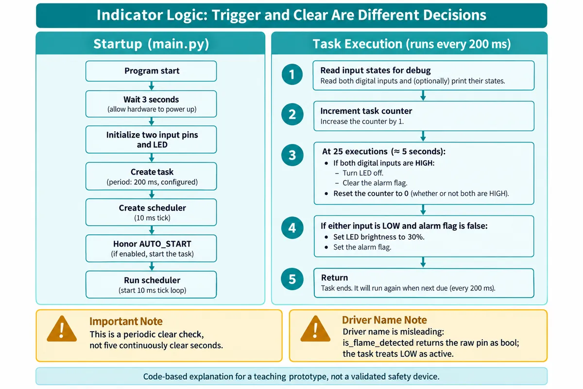
The task runs every 200 ms on a 10 ms scheduler tick. Each run increments a counter. At 25 runs it checks whether both inputs are high; if they are, it turns the LED off and clears its internal flag. It resets the counter at that checkpoint either way.
Then it checks the trigger: if either input is low and the flag is clear, it sets the LED to 30% and marks the indicator active.
if (mq_state == 0 or flame_state == 0) and not alarm:
    led_on()
    alarm = True
One driver method is easy to misread. In the flame driver we used, a method named is_flame_detected() returns the raw input as a Boolean, and its documentation says True means detected, yet the task treats a low input as active. Define polarity from the implementation and the module's real behavior, not the method name.
The clear check happens about every five seconds at the configured cadence. It does not require both inputs to stay clear for five continuous seconds. If they go high just before a checkpoint, the light can clear almost immediately; if they go high just after, it can stay on until the next check. The counter's phase changes the apparent delay.
For a teaching kit that is a good experiment in itself: compare periodic checking with a rule that starts a timer only when both inputs become inactive. The second is a proposal; our code does the first. Decide what you want learners to observe before changing timing constants.
Read the demonstration for what it is
Our recordings show the assembled prototype responding to a flame and to gas, and recovering afterward. They document a demonstration, not a known concentration, a calibrated threshold or a detection range. Turning a module's potentiometer until its indicator changes sets a switching point; it is not a concentration calibration.
For routine logic testing you do not need a flame or a gas source. A controlled, electrically compatible input fixture can drive the high and low combinations safely. We have not built that fixture, but it is the better tool for testing the logic.
Make the next test answer one clear question
Start with the four high/low input combinations and record the LED state for each. Repeat transitions at different points in the 25-run cycle, which makes the trigger and clear rules visible to someone who has never read the code. Log input levels, task timing and output together instead of inferring what each sensor did from the LED alone.
Also decide how the prototype shows that it is running, paused or unable to read an input. In our firmware the flame callback is an empty stub, and the user-button pause control described in the design was never wired up in the main program. An exception message is not a visible fault state. Close those gaps before treating the assembly as a repeatable kit for other people.
The useful result is a demonstration you can explain and reproduce: which input changed, why the indicator came on, and why it stayed on or cleared. That is a solid base for an educational product. It does not establish fire protection, gas safety, fault coverage or reduced false alarms.