
Your prototype already dims a light. You add a buzzer, change its tone, and another output starts behaving differently. Before replacing either module, check whether the two pins share a PWM timer. Separate wires do not always mean separate timing resources.
This matters when a design, music or education team combines several working demonstrations into one device. Each example may work alone while assuming it owns a timer that another example also uses. A short pin plan can reveal that conflict before the wiring becomes a custom board.
A recent Arduino Forum discussion, September 24 to 26, 2026, shows the broader integration question. A mechanical-instrument builder wanted PWM motor control alongside W5500 Ethernet and was considering different boards, including RP2040. Their concern went beyond occupied pins to shared timers and library dependencies. The thread is a planning discussion, not a completed RP2040 validation. The RP2040 timer architecture gives a concrete way to approach that decision.
Two outputs can follow the same clock
PWM means switching a signal on and off repeatedly. Its frequency describes how often the pattern repeats; its duty cycle describes the fraction of each repetition spent high. A dimmable indicator and a passive buzzer may both use PWM, but they need not want the same repetition rate.
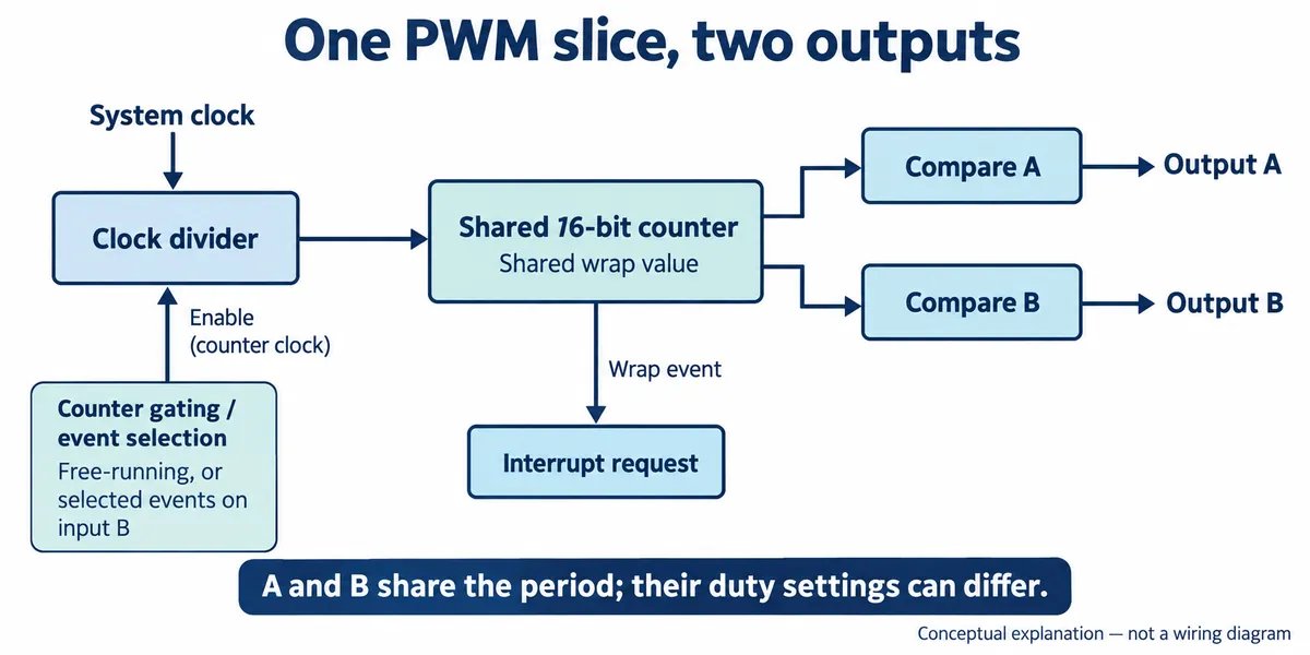
On RP2040, a PWM slice is a small hardware timer with two output channels, A and B. They share a counter, divider and wrap setting, which together set the repetition period. Their comparison settings can differ, allowing different duty cycles at that shared frequency. The input-B gating option in the diagram selects or gates counting events; it is not a universal start signal. The MicroPython RP2 reference documents the pairing and its GPIO mapping.
That explains why setting the frequency for one output can change another. Creating two software objects does not create two hardware timers. Conversely, two LEDs that can run at the same PWM frequency may fit on the two channels of one slice, with brightness controlled separately. Whether that suits the product depends on its actual brightness and flicker requirements.
Read the number and the letter
The RP2040 mapping assigns each GPIO a slice number and a channel letter. Three cases are worth knowing:
- GP0 maps to PWM 0A and GP1 to PWM 0B: different channels, shared period.
- GP2 maps to PWM 1A: a different slice, so a separate period.
- GP16 maps back to PWM 0A: another route to the same output as GP0, not an additional channel.
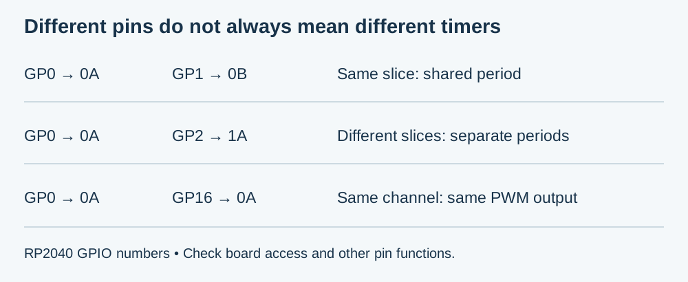
Suppose a proposed design needs a 50 Hz control signal and a 2 kHz tone. Those illustrative requirements cannot be produced as two ordinary fixed-frequency outputs on channels A and B of the same slice. Assigning them to different slices is a candidate solution. The numbers are examples, not universal servo or buzzer specifications; use the connected device's documentation.
Moving a wire only helps if the new pin actually provides a different suitable resource. GP0 to GP16 does not. Nor does a PWM label guarantee that a pin is free: the board may use it internally, or the product may already need its SPI, UART or other function. Record the exact board and GPIO numbering before changing the wiring.
Decide what needs to be independent
Start with a list of the product's outputs and their required behavior. For each, record its repetition rate, what changes during use, and whether another output may share that rate. Add the proposed GPIO, slice and channel, then reserve the pins used by communications and other functions. That gives the engineer something more useful than a count of spare connectors.
Sharing is sometimes intentional. A simple waveform generator, for example, can use both channels of one slice and a filter, because there the outputs are meant to run at the same period. That is a different design goal from generating unrelated repetition rates.
If the plan runs out of suitable independent slices, compare changing the pin allocation, changing how an output is generated, or adding a dedicated peripheral. Include firmware complexity and the required waveform quality in that choice. More PWM-capable pins alone do not show that a replacement board has the resources the product needs, and this RP2040 mapping should not be carried to another chip without checking.
Check the combined behavior before fixing the wiring
First confirm the expected period and high time for each output on its own. Then run them together and change one setting at a time while observing both signals. A scope or logic analyzer can distinguish a changed repetition period from a supply disturbance or a software scheduling problem. An audible change or a flickering lamp is evidence of a symptom, but it does not identify the cause.
The MicroPython PWM API warns that a frequency change can affect other objects using the same generator. Include the libraries that create those objects in the review, because a driver may initialize PWM internally. Record the board, firmware version and final pin allocation alongside the observations, so another person can reproduce the combined setup.
For an interactive exhibit or mechanical instrument, finish by running the intended interaction with its other functions active. Does changing a tone alter an indicator? Does a control output keep the timing its receiver requires while communications run? These are proposed validation questions, not results we have recorded; they turn a resource map into a test of the product people will actually use.