
You are adding a radio, sensor or small screen to a working development board. A test sends bytes and reads back exactly the same values. That is encouraging, but once you connect the module it still gives no useful response. What did the first test actually prove?
This is a common integration question. In a May 2026 Adafruit forum discussion, someone building a small weather station reported that SPI loopback passed while a radio module's version register kept returning zero. The thread did not establish a measured root cause. It does show why a successful self-test and a successful conversation with a peripheral need separate evidence.
We ran a PIO-based SPI loopback on our bench to see the difference: send the numbers zero through seven, read them back, and capture the signals with a logic analyzer. This note walks through what that run showed, and the next test a team needs before relying on an attached module.
First, understand who sent the answer
SPI is a clocked connection: the controller supplies timing, sends bits on an output line and samples an input line. A separate chip-select signal usually tells the intended peripheral when a transaction is taking place. Those signals must agree with the peripheral's own interface requirements.
In our test, both the output and the input used GPIO10. The program reads back the signal it produces on that pin. No external sensor or radio generates the returned values. Raspberry Pi's PIO loopback example uses the same general arrangement: serial input and output assigned to one GPIO.
The board was a WIZnet EVB-Pico2 running MicroPython 1.23.0. Clock was on GPIO11 and chip select on GPIO12. For the analyzer, data went to channel 1, clock to channel 2 and chip select to channel 0, with a common ground and compatible input levels. The console printed [0, 1, 2, 3, 4, 5, 6, 7] every second. Because both directions share GPIO10, that is self-readback, not a reply from a device.
Send a short pattern you can recognize
PIO is a small programmable hardware sequencer on the RP2 chips. In our setup it supplied the bit timing, while Python chose the bytes and started each exchange through a small wrapper class our team wrote. The test called its combined write-and-read method with the eight-byte list, printed the result, and slept for one second.
The clock mode was mode 0: the clock rests low and input data is sampled on the rising edge. The test requested a 1 MHz bit clock. The one-second sleep between exchanges is a separate application decision; it does not change that clock to 1 Hz.
We configured the analyzer's SPI decoder to match: most significant bit first, eight bits per word, CPOL 0, CPHA 0 and an active-low enable. An analyzer does not discover your intended protocol settings for you. The MISO field was left unassigned, so the decoded view shows the outgoing data line. It is not a separate capture of a peripheral's reply.

The trace shows eight clock bursts and byte labels from 0x00 to 0x07 (one label collapses to an ellipsis at this zoom). A terminal printout alone would hide that timing information.
Read the clock and the whole transaction separately
Zoomed into one clock period, the capture measured a 1 microsecond period, 500 ns pulse width and 50% duty cycle. That is consistent with the requested 1 MHz clock. It describes the bits inside a burst, not the rate at which useful application data moves.
At a wider scale, the chip-select signal repeated about every 1.00094 seconds. Most of that interval is the program's one-second pause. Within an exchange the byte groups also have gaps, visible in the trace above, because Python supplies and retrieves data one byte at a time.
For a slow configuration command, those gaps might be acceptable. For a display update or a device with specific transaction timing, the receiving device's requirements decide. Keep the clock measurement, the complete transaction capture and the decoded values together; none substitutes for the other two.
Tie the passing test to the method it exercised
The combined write-and-read method puts one byte into the transmit queue, waits for one received value, and appends its low eight bits to a list. This pairing matters: it both supplies data and takes received data out again.
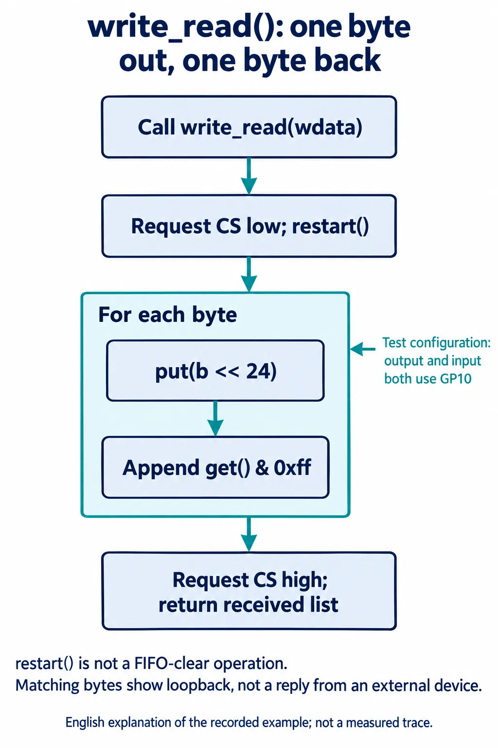
A FIFO is simply a queue between Python and the hardware sequencer. The MicroPython 1.23.0 rp2.StateMachine reference separates putting data into that queue from retrieving it: get() waits when the receive queue is empty, and put() may wait for room in the transmit queue.
So the matching console values support this particular exchange. They do not test every method in the class. When we read the code afterward, we found that the separate write-only method does not drain the receive queue or explicitly wait for the final transmitted bit. The separate read-only method takes received values but does not queue the outgoing data needed to produce new clock pulses. A code comment describing restart() as clearing the receive FIFO is also misleading: the documented restart resets internal execution state, not the FIFO contents.
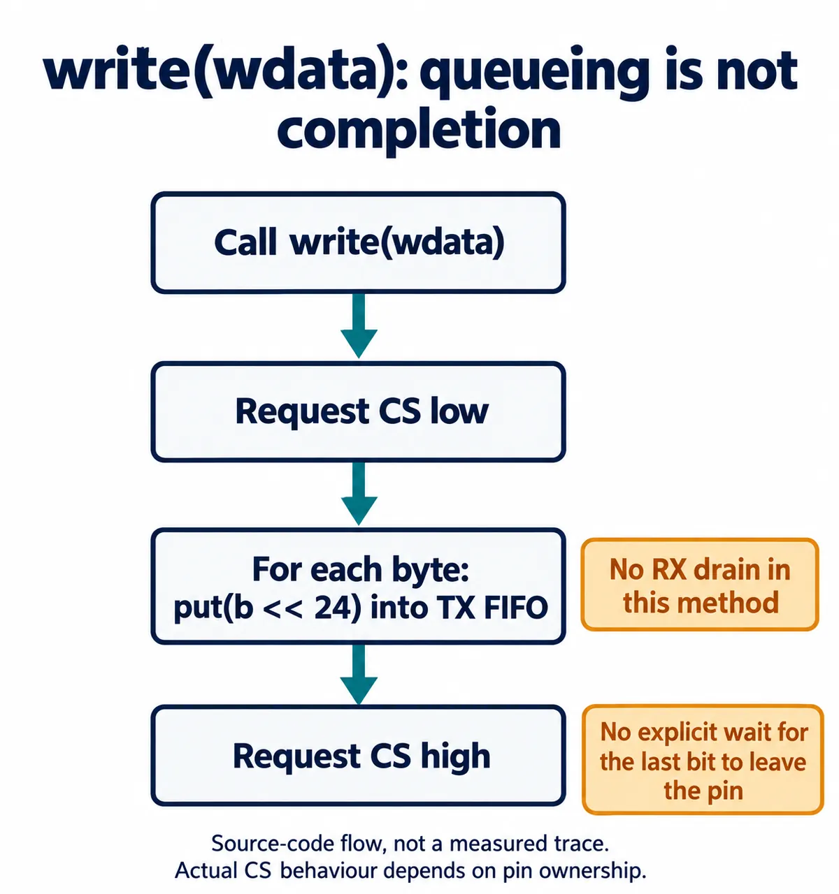
One more detail needs resolving before adapting this code: the PIO program assigns two side-set pins starting at GPIO11, while the Python wrapper also configures GPIO12 as a chip-select output. Decide which mechanism owns that pin and verify the resulting waveform. A loopback cannot settle chip-select behavior for a real device, because its data path does not need any device to be selected. These are findings from reading the code; we have not yet tested a revised version on hardware.
Make the next test ask the module a real question
Once the loopback is understood, replace self-readback with the peripheral's documented connection. A conventional four-wire SPI device has a separate return line; do not keep the same-pin assignment because it worked in this test. Confirm power, logic levels, reset requirements and the actual board pin mapping before attempting communication.
Then choose the smallest useful transaction from the device documentation. It might be reading a known identification register, checking a status field, or writing a reversible setting and reading it back. Not every device provides the same kind of response. Capture chip select, clock, outgoing data and incoming data together, and compare the complete exchange with the device's required command and response format.
That gives a much clearer handover than "SPI works": the controller passes a defined loopback test, the attached module answers a defined command, and the relevant signals have been checked. Only then does it make sense to move on to the full application, such as collecting measurements, transmitting a packet or updating a screen.