
A turning pointer, a moving exhibit or a small rotating display can make a product idea much easier to understand. Getting a motor to spin is the first useful milestone. The next question is harder: when you ask the mechanism to move, stop and come back, does it actually return to the right place?
A small geared stepper motor is a convenient way to explore that question in a first moving prototype. On our bench we drove a five-wire 28BYJ-48-5V motor from a GraftPort-RP2040 controller board through a GraftSense I2C stepper-driver board running MicroPython. This note covers what that setup showed, what it did not show, and what to check before you build a custom mechanism around it.
Choose the movement before choosing the motor
For a lightweight pointer, the questions might be whether it reaches each mark and whether the motion looks smooth. A display turntable adds the object's weight, balance and inertia. An arm that lifts something has a different load again, especially when it extends. Start from the motion and the load your user will see, not from a step-angle number.
The driver board we used is intended for five-wire unipolar motors. Its motor connectors are not interchangeable with a four-wire bipolar motor just because both are called steppers. The small geared motor is good for exploring motion; our test does not establish how much of your proposed mechanism it can move.
Follow the control path and the power path
The controller talks to a PCA9685 over I2C. That chip sets output states; ULN2003 driver stages switch the motor's coil currents, fed from an external supply. The microcontroller controls the sequence without supplying coil current through its GPIO pins.
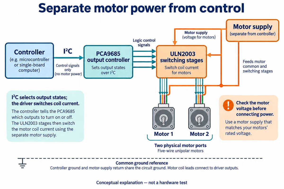
The PCA9685 is a 16-channel output controller, as described in NXP's datasheet. That does not make this board a sixteen-motor driver: it has two motor ports. Likewise, a single-channel current rating for a transistor array is not a verified continuous-current rating for the whole board. Choose the supply and load from the actual circuit, the motor requirements and thermal checks.
When reading the circuit, note that a ULN2003's COM pin is the common connection for its clamp diodes, used with inductive loads. It is not a logic-supply pin. TI's ULN2003A datasheet explains this role; the part actually fitted to a given board still needs its own manufacturer's specifications.
The driver switches four coil paths in a sequence. A connector that physically fits but presents those paths in a different order can produce the wrong motion or no useful rotation. Check your motor's actual lead arrangement instead of trusting a color sequence from another motor.
The bench test
Our setup was the controller board, the driver, one 28BYJ-48-5V motor and an LM2596 adjustable supply module. This motor needs 5 V at the driver's motor input. Set and measure the supply before connecting it. A 12 V version of the same motor family exists; that is not permission to apply 12 V to the 5 V part.
The driver connects to the controller's I2C0 interface, with GPIO 4 as SDA and GPIO 5 as SCL. The motor goes to the port marked as motor 1. The I2C connector powers the control side; the separate VIN terminal supplies the motor side. Keep the ground connections consistent with the board schematic.
An I2C scan is the first software check. It tells you whether a device acknowledges an address, before you try any motion command:
from machine import Pin, I2C

i2c = I2C(0, sda=Pin(4), scl=Pin(5), freq=400000)
print([hex(address) for address in i2c.scan()])
On our bench the scan found two devices and identified the PCA9685 at 0x4a. That is evidence of communication, not of motor angle. The address depends on the board's address-selection solder pads, so check those pads before comparing your result with ours.
What the motion commands meant
The test program first requested continuous single-phase motion at a speed argument of 10, waited ten seconds and stopped. It then requested a finite move: motor 1, backward, single-phase mode, a speed argument of 100 and 1,000 sequence steps. In the driver, the timer period is 1000 / speed milliseconds, so the speed argument is a requested sequence-update rate, not revolutions per minute.
The motor shaft turned and the driver's indicator LEDs changed state. That is an unloaded motion demonstration, with no calibrated position, torque or repeatability result. To choose a motor for your assembly, you still need to watch it with the intended load attached and the intended pattern of starts, stops and reversals.
If you reproduce this, check the software first: confirm that every driver file you install contains its implementation, and that any PWM frequency the stepper code requests is within the PCA9685's documented internal-clock range. Use a checked, matching driver version before a powered motion test.
A smaller commanded step does not prove a more accurate mechanism
The driver offers three coil sequences: one phase at a time, two phases at a time, and a half-step sequence that alternates between them. They explain how the motor is driven. They are not a measured output-shaft angle on a geared motor.
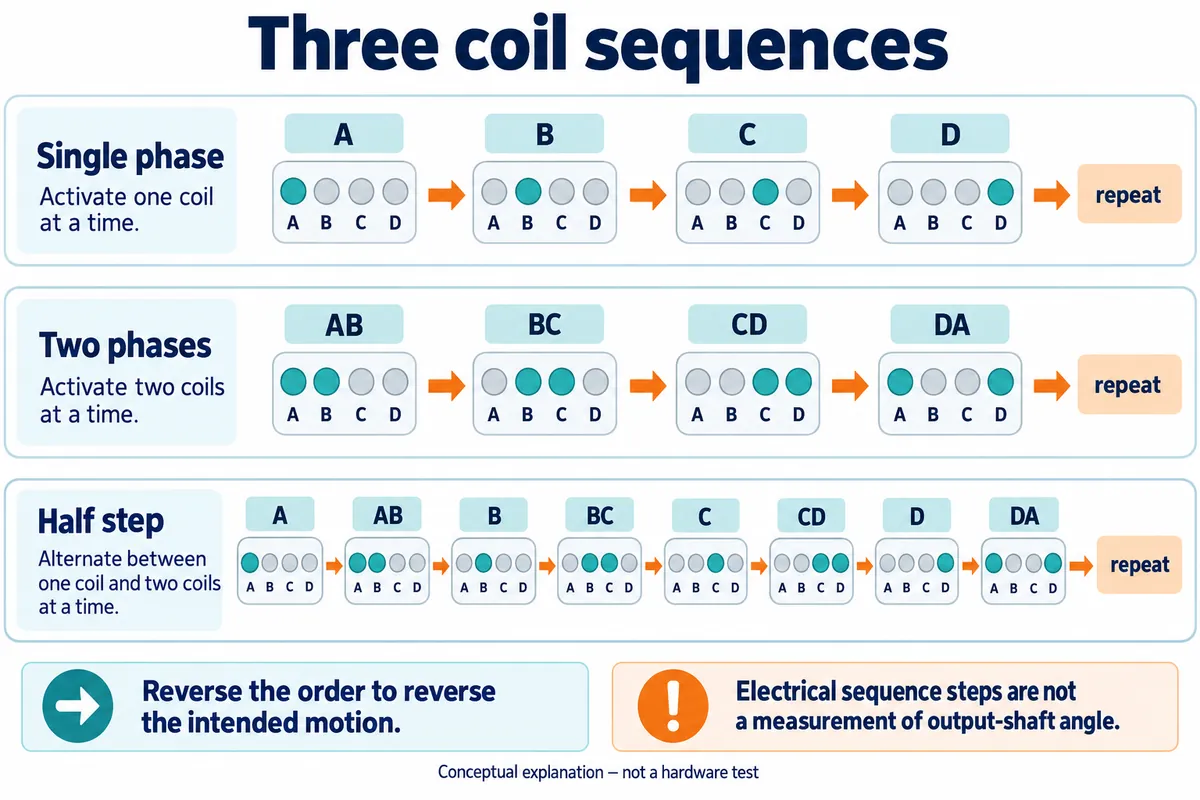
To turn sequence steps into an expected output angle, you need the motor's step behavior, the drive mode and the actual gearbox ratio. Then you need to check whether the output follows that expectation under load. Gear slack can appear when reversing, and a motor can fail to follow a requested step when the load or speed is too demanding. A software step counter sees neither event.

A February 2024 Arduino forum thread about a clock build shows why the motion pattern matters. The builder reported that continuous rotation worked but the repeated short moves of a clock did not add up as expected, and later reported improvement after changing the motion function. The thread does not establish one cause or fix, but the lesson holds: test the start-stop behavior your product actually uses.
Add a reference, then test the real movement
Start with a visible pointer and a fixed reference mark. Command the same move several times, approach the target from each direction, and see whether it returns to the mark. Then repeat with the real mechanism attached. This separates a movement demo from a test of the assembly you plan to build.
If the product needs a known position after power-up, decide how it will find it. A home sensor or limit switch can provide a reference; a step counter cannot discover where a user left the mechanism while the power was off. Make that choice before the enclosure and mounting points are final.
Also decide what "stop" means. The stop functions in the driver we used turn all coil outputs off. That removes active holding torque, which is different from keeping the coils energized to hold position. A mechanism that can move under gravity or be pushed by a user needs that difference weighed against power consumption and heating.
For the next prototype, record the load, travel, direction changes, intended move time and the number of successful repeated cycles. Check temperature and recovery after a restart, and run the buttons or display updates that will operate alongside the motion. These are checks to run on your assembly, not on an unloaded bench motor.