
A sensor is often most useful where there is no convenient power socket: beside a planter, on a sheltered balcony or at a temporary outdoor installation. Adding a small solar panel seems like a straightforward way to avoid regular charging. The harder question is whether it can collect enough energy where you actually intend to put it.
For a team moving from a working sensor demo to a field trial, that question is best answered before the enclosure is finished. The panel needs light, the sensor needs a suitable measurement location, and the battery needs enough reserve for the periods when the panel contributes little. Those requirements may point to different mounting positions.
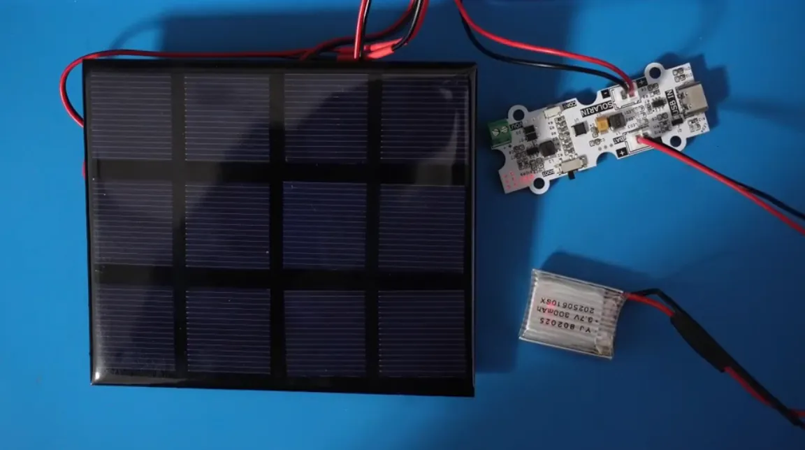
On our bench we assembled a small panel, a lithium-polymer cell and a GraftSense power-management board built on ST's SPV1050. This note covers what that setup tells you and what to check before calling a prototype self-sustaining.
Put the panel and the sensor where each can do its job
In an August 2024 AirGradient forum question, a prospective user wanted to install an outdoor monitor without an outlet. The balcony with power received direct sun, while the preferred window ledge stayed in shade. That is a concrete design conflict: the convenient location for power is not necessarily the right location for a measurement.
For a temperature or humidity node, consider a separate panel and sensor housing rather than assuming one small box must do everything. It adds cable routing and mounting work, but lets you evaluate light exposure independently of sensor placement.
Start by observing the proposed panel location through the day. Record shading from walls, trees and the enclosure itself. Then measure there; a panel's size or a voltage reading under a desk lamp cannot tell you how much energy it will collect over a winter day.
The four connections on the board
The board has separate connections for the solar panel (SOLARIN), the battery (BAT), USB charging (USB IN) and the external load (VOUT). Our setup had the panel and battery connected; it did not include a working environmental sensor on the output.
Inside, the SPV1050 handles energy harvesting and battery management. A TP4057 circuit provides a separate USB charging path, and an ME2159 stage produces the nominal 5 V output. That distinction matters when reading a specification: a limit for one chip is not automatically the current available at the board's final output.
The board documentation advertises up to 70 mA from the solar charging arrangement. Treat this as a capability to investigate, not a current the panel delivers continuously. We have no charging-current log, panel power curve or daily energy measurement for it, and we have not shown how much load the assembled board supports through a discharge cycle.
No driver code is needed, and in sufficient sunlight the board charges the cell. That makes the bench setup simple to assemble, but observing connected parts is only the first step. To evaluate a sensor product, record the current entering or leaving the battery and the voltage supplied to the actual load.
Check startup before planning unattended operation
When a battery is first connected without solar input, the board needs a manual activation step with a button. The board's documentation labels that button inconsistently between the written instructions and the schematic, so identify the actual switch by board revision and circuit rather than copying a switch number.
For an unattended sensor, the important follow-up is whether it can recover after a long dark period. A device that works once you press a bench button may still require someone to visit the installation after the battery runs down. Test startup with a charged battery, recovery from the intended low-battery shutdown state, and operation as light returns.
ST's SPV1050 documentation distinguishes cold-start conditions from the lower input voltages at which an already-running circuit can keep harvesting. Our carrier uses a boost configuration, while ST also shows a buck-boost reference design. Do not transfer that reference's wider input range to the boost carrier when selecting a panel.
A charging circuit helps collect energy; it does not set the weather
Maximum power point tracking, or MPPT, adjusts the panel's electrical operating point to help extract the available power. It cannot compensate for a location that receives too little light for the load. With this chip, external resistor settings also form part of matching the harvesting circuit to its source.
Think of the battery as a reserve between collection and use. During a productive period the system may replenish it; during darkness the load draws it down. The useful question is how that reserve changes over several representative days, including the poorer ones, while the sensor does its intended work.
A simple energy budget makes this easier to discuss:
- Estimate or measure the energy used by each sensing and radio event, and multiply by the events per day.
- Add the energy consumed while waiting.
- Compare that total with the energy actually collected after conversion losses.
Use a common measurement point, or account for the losses consistently: battery current and 5 V output current are not the same quantity. Reducing the frequency of a nonessential update may help more than changing the charging board, so decide how often users need a result before assuming the sensor must stay fully active.
Resolve the board version before treating it as a build recipe
The charging details on this board need reconciliation before replication. The USB charger drawing and its datasheet do not give a consistent, verified charging-current setup, and the charger specification lists a charging voltage that differs from the module summary. Confirm the fitted charger, its current-setting circuit and the cell's charging limits together.
Likewise, check the panel's open-circuit voltage under the conditions it may encounter, not just its nominal label, against the limits for the actual carrier configuration. A panel used successfully with a different solar controller is not automatically suitable here.
These are specific checks on this design, not reasons to abandon the application. You can measure your sensor's load, study the installation position and define the desired behavior while the charging circuit is reviewed. We have not confirmed that these discrepancies are corrected on current boards.
Make the field trial answer a decision
Use the complete intended load and log three things together: available solar input, battery condition and device operation. Record the sampling schedule and radio activity too, so a successful day can be compared with one that produced missing readings. Keep USB charging out of a solar-only test, or record its contribution separately.
Test the physical arrangement you intend to install. Panel orientation, shading and a protective cover all change what it collects. For the battery, verify that charging is permitted over the temperatures the enclosure reaches. Our open bench assembly says nothing about weather resistance or a temperature-qualified outdoor build.
For the first trial, define a modest outcome such as "collect the required readings through this observed weather period without manual charging." Then decide what would justify a larger panel, a lower update rate, a different power circuit or an accessible charging port. Report the observed duration and conditions; a few successful days do not establish performance through every season.