
Your robot head turns on the bench. Now you want it to look toward someone, pause, and speak. Before adding that sequence, answer a smaller question: how does the controller know the movement has finished?
A delay can make a demonstration look convincing. A number printed as "Angle" can look even more convincing. But that number may simply repeat the position you requested. For a team moving from a loose servo to an assembled mechanism, knowing what comes back over the wire is a step toward dependable behavior.
On our bench we drove one Hiwonder LX-1501 bus servo through a GraftSense UART servo interface board, with an external supply and a short MicroPython program. The run demonstrated movement and reading back the movement settings. This note separates those results from the next test: measuring whether the mechanism actually arrived.
Start with one moving part
This is a practical concern for expressive hardware. In an October 2026 robot-head project, the builder described working on smoother motion, neck stress and travel limits once the head was moving. That project used a different, PWM-based controller; it illustrates the integration problem, not a recommendation for this module.
Our setup was simpler. One LX-1501, already assigned ID 4, connected to a GraftPort-RP2040 controller. A separate LM2596S supply module fed the servo interface with 5 V. The controller talked at 115200 baud on UART0, GP16 transmit and GP17 receive.
The connector labels are written from the controller's point of view: controller TX goes to MTX, controller RX goes to MRX. Do not cross them a second time. Check connector orientation and a common ground before applying power; "three wires" describes the interface, not a universal pin order across servo brands.
A bus can chain several servos, but that does not mean this board powers several moving servos at once. Its schematic notes a one-servo-at-a-time drive limit, and our run used one. Size power and wiring again before extending the setup.
Why this servo needs an interface
A controller UART has separate transmit and receive pins. This servo shares one data line for both directions, so controller and servo must take turns. The module's buffer and inverter circuit handles that; software then sends a request addressed to the intended servo.
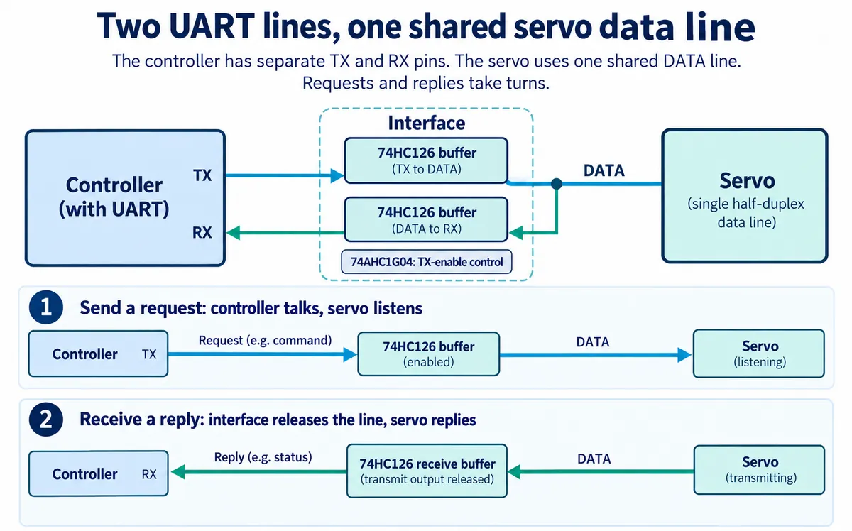
The circuit uses 74HC126 buffering with a 74AHC1G04 inverter in the transmit-enable logic. That differs from wiring an ordinary PWM servo signal, and it is not a universal adapter for every product called a "bus servo." Match the servo protocol and electrical interface before reusing the design.
What our test program did
We used our team's MicroPython serial-servo driver. The program repeated two moves on servo ID 4: request 0 degrees over 1000 ms, wait two seconds and read back; request 90 degrees over 1000 ms, wait and read back. ID 4 belongs to the servo we tested; another unit may need a different address.
The terminal printed 0 and 90 with a time value of 1000, matching the requested settings, and the servo visibly moved between the two positions. That is a useful first milestone: the controller can issue moves and get a reply containing the move parameters. It does not establish angular accuracy or performance with a mechanism attached.
Read the right value before calling it feedback
The read-back call in our program sends protocol command 2. Hiwonder's bus servo protocol (pages 4 and 8) defines that command as reading back the angle and time sent by the last move command. Command 28, SERVO_POS_READ, is the separate operation for current position. The two replies answer different questions.
Think of ordering a delivery and checking the address on the order: the right address does not tell you the parcel arrived. Likewise, a returned target of 90 degrees does not show where the shaft is now. The driver also has a function for the current-position reading, but our test loop did not call it.
For the next bench test, record the requested angle, the current-position reply and the sample time separately while watching the shaft. Treat a missing reply as "unknown," not zero degrees or the last successful value. We have not run that tracking log yet.
A position reply still describes the servo's own measurement. It does not prove that a slipping horn, a flexible linkage or an attached head reached the intended pose. Compare the visible mechanism with the reported position before deciding which signal should allow the next action.
The driver's receive path also needs work before that signal drives product decisions. It reads the UART buffer once after a short wait; it does not assemble partial packets against a deadline or check that a response belongs to the requested servo ID. Keep that in mind when adding devices or handling lost replies. We have not rerun the hardware with a revised driver.
Test the assembled movement, then decide what to change
Once the unloaded setup works, attach the intended mechanism with a conservative movement range. Check direction, clearances and the visible endpoint before repeating larger moves. Log commanded and reported positions during ordinary operation, together with communication failures. That gives you evidence for changing the motion, mounting or power system instead of guessing from how it looks.
The module includes an SS34 diode, a resettable fuse and bulk capacitance. Those parts do not tell you how much current is available to a mechanism. In particular, the fuse's 1.5 A hold and 3 A trip ratings are fuse characteristics, not permission to draw 3 A continuously. Measure the supply at the servo during the intended movement and check the whole power path for the real load.
The useful result is a clear condition for the next action: a fresh, plausible position reading within your chosen tolerance, plus whatever mechanism checks your application needs. If that condition is not met, the controller should follow a defined timeout behavior. Choosing and testing that behavior belongs to the assembled prototype, not to a two-position bench demonstration.