
Your prototype already sends useful data to a computer over a serial connection. Now you want the computer somewhere else in the room, or you want an existing installation to feed a local monitoring program. A serial-to-Ethernet bridge can let you keep much of that working device interface. The important question is what the bridge carries, and what the software at the other end still has to understand.
For a small team adapting a sensor, an exhibit controller or a workshop instrument, a good first milestone is modest: make one recognizable message reach the intended computer over the network. Then test the return path separately. On our bench we did this with a WCH CH9121 bridge on a GraftSense carrier, driven from a Raspberry Pi Pico running MicroPython. Numbered messages reached the computer. The controller, meanwhile, kept reporting that nothing came back, which is exactly the kind of result worth planning around.
The bridge carries bytes; your application gives them meaning
Imagine an instrument that sends weight=12.4 over its serial port. A transparent bridge can carry those bytes through a network connection. It does not turn them into a dashboard reading, a database entry or a command another product understands. That is the job of software that knows the device's format.
The same confusion shows up in a Reddit discussion about how serial-to-Ethernet adapters work: the poster saw ASCII data carried over a network and then presented to software as a virtual COM port, and wondered why it was still treated as serial. The practical question is usually how to preserve an existing software interface, not how to add a network socket.
Before choosing a bridge, find out what the receiving software accepts. A new program can read a TCP connection directly. An older application that only opens a COM port may need a compatible virtual-port tool. A system that expects a specific higher-level protocol needs a real translation or gateway; a byte bridge does not provide that. In our test the receiver was a network debugging tool, which let us inspect the raw bytes first. The CH9121 has two UART channels; we only used one.
Keep the existing serial connection understandable
We connected the Pico's UART0 transmit pin GP16 to the carrier's MTX and receive pin GP17 to MRX, at 9,600 baud. On this carrier the M means the host microcontroller: MTX goes toward the module's receive input, and MRX brings the module's output back.
Check the electrical interface as well as the labels. Our carrier uses logic-level UART. An existing instrument with RS-232 or RS-485 needs the matching electrical interface; its connector cannot go straight onto these pins. The carrier also takes 5 V into a 3.3 V regulator, which is not the same as putting 5 V on the CH9121 itself.
The carrier exposes a CFG input separately from the four-wire power and UART cable. Our example code expected GP19 to drive configuration, while our setup notes said to press the CFG button, and the four-wire cable did not carry CFG. Pick one control method and verify it is actually wired before running a configuration step.
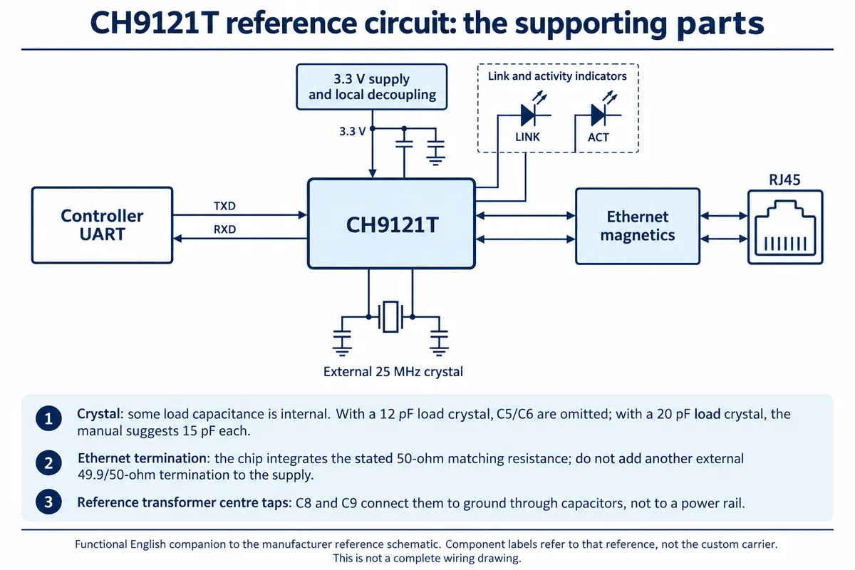
The manufacturer's reference circuit shows why a bridge is more than a jack wired to serial pins: Ethernet magnetics, supply decoupling, an external 25 MHz crystal, and termination that is already inside the chip. Those details matter when you move from a carrier board to your own PCB. For the first communication test, the existing carrier is enough.
Decide which end starts the network connection
We set the CH9121 as a TCP client and ran a TCP server on the computer. The bridge opens the connection; the computer waits for it. "Server" here is the role of a program on a computer in the room, not a cloud service.
The bridge's destination IP and port therefore point to the computer and its listening program, and the bridge also needs its own valid address. Keep those identities separate: a correct destination will not fix an invalid local address or a program listening on the wrong network adapter.
Our records showed how easily these drift. The configuration window showed TCP client mode, a destination port of 2000, serial settings of 9,600 baud, 8 data bits, no parity and 1 stop bit, and DHCP enabled. But the gateway in the program differed from the gateway in the configuration window, and the computer later logged the client at yet another address. For your own test, write down the computer address, bridge address, subnet and listening port together at the time of the test, instead of assembling a configuration from different screenshots.
Configuration is a separate operation from sending data
WCH's configuration documentation describes holding CFG low to accept configuration commands at 9,600 baud and releasing it to return to transparent transfer. Configuration bytes are meant for the bridge; device bytes are meant to pass through it.
Our program first used a MicroPython driver derived from wybiral's micropython-ch9121 (MIT) to select TCP client mode and set network parameters, then switched to a plain UART loop. That configuration path is not a validated deployment routine. Its wait for a configuration response had no overall timeout, and the example did not explicitly run the documented save and apply sequence. Its reset() sends command 0x02, while the command manual lists 0x0D to save settings and 0x0E to apply them and reset. A function named reset() is not evidence that settings were saved.
For a first reproduction, use the manufacturer's configuration tool or a checked routine, read the settings back, and confirm they survive a power cycle. Keep the exact driver archive with your project too: our installation notes, archive name and the driver's internal version string did not all agree.
Read the result in each direction
After configuration, the loop sent a numbered text string, waited 0.1 seconds, checked the UART receive buffer, then waited two more seconds before the next message:
uart.write(f"Test message {count}".encode())
time.sleep(0.1)
if uart.any():
    print("Received:", uart.read(uart.any()))
else:
    print("Received: No data")
The network tool on the computer, listening on port 2000, showed the numbered strings arriving. That is visible evidence for controller to UART to bridge to network to computer.
The Pico console, at the same time, printed "No data" after every message. That does not cancel the outgoing result; it says this buffer check found no returned bytes. We did not demonstrate a reply at the controller, and calling the test message a "loopback" did not make it one.
The next test should send a distinct reply from the computer and capture it at the controller, for example echoing the sequence number so the two directions can be matched. Keep listening over a defined interval instead of treating one 100-millisecond check as proof of a broken link, and log a late reply separately from no reply.
Also decide how complete messages are recognized. Our example wrote strings without a terminator and printed whatever bytes were available. Real instrument data needs the device's framing rules, such as a delimiter, a fixed length or a length field, and code that handles partial input. The bridge does not supply those rules.
Choose the next milestone around the device you have
If the goal is collecting readings from an existing instrument, first save a known-good local serial capture, then compare the network data with it. If the goal is control, add an explicit response that tells the computer whether the action was accepted. Sending bytes and completing an action are different milestones.
Once both directions work, interrupt the connection on purpose: restart the listening program, unplug and replug the network cable, and power-cycle the bridge. Check whether the software notices the disconnect, whether it reconnects and whether old data shows up as if it were new. We have not run these tests yet.
Record the exact package as well. WCH distinguishes the CH9121T from the CH9121A, including different CFG pin numbers, so an example written for another package or carrier may use different control connections. For a first installation trial, settle who assigns the network address, which application receives the bytes, how an operator recognizes a disconnected device and where the Ethernet cable fits in the enclosure.