
The sensor sends sensible readings when it is the only thing your prototype does. Then you add a display update, save a file or process a larger batch of data, and some readings disappear. Raising the serial speed can make it worse: the receiving side gets less time to make room for the next byte.
For a team building a logger or connecting two modules inside a product, the useful question is whether the sender can wait when the receiver is busy. There are two common ways to ask for that pause: separate RTS/CTS signals and XON/XOFF control characters. This note is a design reference for a MicroPython prototype on the RP2040; we have not run a flow-control stress test for it. It covers what the prototype needs to support and what to test next.
The situation appears in a May 2026 embedded-development discussion: a developer reported receive overruns between an STM32 controller and a Linux processor with hardware flow control disabled. Replies proposed buffering, DMA and flow-control changes, but the visible thread did not establish a final tested fix. It shows the integration problem, not a setting that repairs every serial link.
A buffer gives you time, not unlimited capacity
Serial bytes first arrive in a small hardware buffer, a FIFO (first in, first out). A driver may move them into a larger software buffer, and the application then consumes them. Each stage needs room for incoming data. An overrun happens when new data reaches a stage that cannot hold it.
Here is a calculation, not a device measurement. At 115200 baud with eight data bits, no parity and one stop bit, each byte takes ten bits on the wire, so continuous traffic brings in 11,520 bytes per second. If a buffer has 256 bytes free and nothing drains it, that space lasts about 22 milliseconds. That describes those assumptions; it is not the pause tolerance of any particular MicroPython board.
A larger buffer absorbs a longer temporary pause. It cannot fix a permanent mismatch where data arrives faster than the application processes it. The options are to consume faster, send less, agree to discard some data, or make the sender wait. Flow control is the last option.
Use RTS and CTS to signal available space
On the RP2040, the receiver's RTS output connects to the sender's CTS input. The receiver indicates whether it can accept more bytes, and the sender checks that input before continuing. For traffic in both directions, each side has the corresponding output and input. These signals are in addition to TX, RX and ground.
The names suggest a request-and-approval exchange for every message. Automatic receive flow control is simpler than that: it only signals whether there is space.
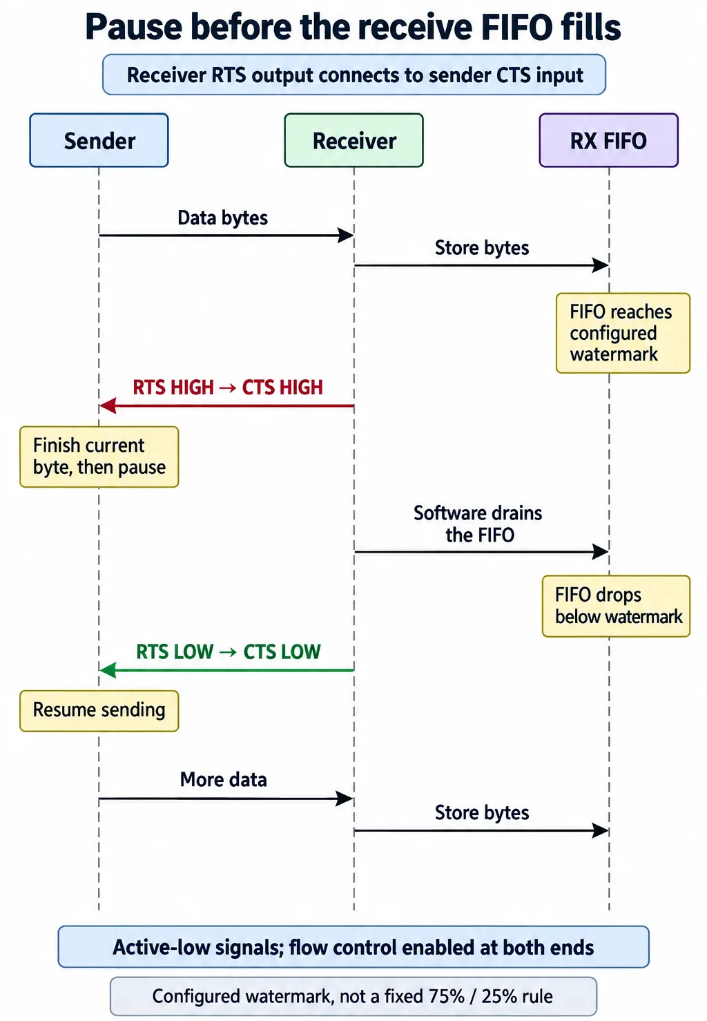
For this peripheral, the signals are active low. When the configured receive-FIFO threshold is reached, the receiver raises RTS, which raises the connected sender's CTS input. A sender using matching CTS behavior finishes its current character before stopping. Once the receiver drains below the threshold, RTS goes low and transmission can resume. The RP2040 datasheet, section 4.2.4 describes this sequence.
That last character matters. A pause does not remove bytes already on the wire, so leave capacity for the peer's documented stopping behavior and check it with the real interface. Fixed percentages such as 75% and 25% often seen in teaching diagrams are illustrations, not the RP2040's stop and restart settings.
The RP2040's UARTIFLS register selects the receive-FIFO threshold (one-eighth, one-quarter, one-half, three-quarters or seven-eighths). Changing the threshold changes when the hardware reacts; it does not enlarge the FIFO. If a high-level driver owns the UART, configure it through the supported interface instead of changing registers underneath it.
Both ends and the cable must support the pause
A connector that carries only TX, RX and ground cannot carry RTS/CTS. Check the module and adapter pinouts before choosing a cable or finalizing the enclosure connector. Also check whether labeled control pins are already used for reset or programming; that is a different use and should not be assumed interchangeable.
For MicroPython, the version 1.23 UART reference treats rts as an output, cts as an input, and uses the flow setting to enable them. UART.RTS enables receive-side signaling; UART.CTS makes transmission obey the CTS input. Both can be selected together. Supported parameters and valid pins depend on the port and board, so use the documentation for the installed firmware.
On a computer, the application has to enable the intended mode too. pySerial, for example, has separate rtscts and xonxoff options. A wire on CTS does not help if the sender ignores it. Enabling CTS control without a valid input can also make a working transmitter appear to stop completely.
Keep the hardware FIFO and the application's own queue separate in your reasoning. The MicroPython 1.23 RP2 driver moves received bytes into a software ring buffer while space remains. That is a different stage from a list or queue your program fills afterwards. A correctly paused UART cannot recover records the application has already discarded.
When extra control wires are unavailable
Software flow control sends the pause request as a special byte in the return direction: XOFF is 0x13 and XON is 0x11. The receiver sends XOFF to ask the sender to stop, then XON when it can accept more. Both ends must recognize the convention and have a path to send the control byte back.
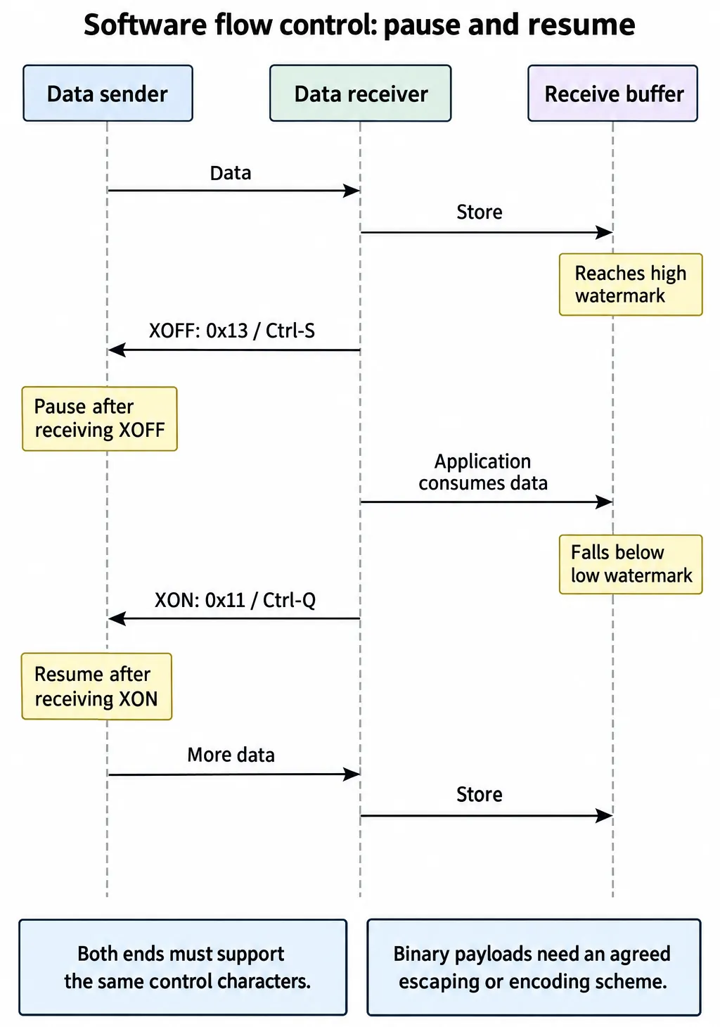
This only works when it fits the existing protocol. Binary data may contain 0x11 or 0x13 as ordinary payload, so the two ends need an agreed encoding or escaping rule. Do not insert XON/XOFF into a commercial module's binary stream unless its documented interface supports it. MicroPython's flow flags configure hardware flow control, not an automatic XON/XOFF parser.
If a module cannot pause at all, look for a lower reporting rate, shorter bursts or a request-and-response mode. If its data must stay continuous, the receiver and its storage path need enough sustained capacity. Dropping old readings may be fine for a live indicator and unacceptable for a recording; make that a product decision, not a side effect of a full buffer.
Test a deliberate pause before trusting a busy demo
For the next bench test, send a known sequence of numbered records. Run the display and storage operations the prototype will really run, then compare sent and received records. Watch the data and flow-control lines together so you can tell whether a pause request occurred, whether the sender honored it, and whether reception resumed.
Add one controlled receiver stall, long enough to trigger the flow-control response without disabling the mechanism you are testing. Record extra bytes after the stop indication, missing or repeated records, and the time to resume. Then test restart behavior when the peer is switched off or the connection breaks. These are proposed checks; we have no measurements from them yet.
The goal is not just to make an overrun warning disappear. It is to know how the link behaves while the product does its real work. Flow control moves waiting time back to the sender, so the sender also needs a defined timeout or waiting state. A system that keeps every byte but blocks its user interface indefinitely still needs work.
Before shrinking the prototype onto a smaller board or a fixed harness, decide whether to keep the extra control connections, based on expected traffic, measured pauses and behavior under load. Reserving pins now is much easier than discovering later that the finished connector cannot carry the signal the sender needs.