
Your prototype flashes a light at a steady pace. Then you add a display update or a network request, and the rhythm changes. If another device depends on that signal, the question becomes more useful than "How do I blink an LED?": which part of the system should own the timing?
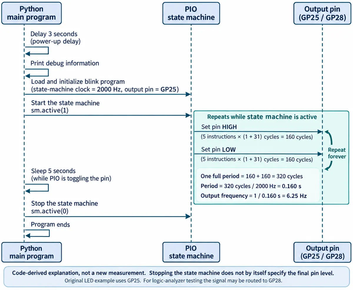
On an RP2040 board, programmable I/O, or PIO, can run a small sequence of pin operations independently of the Python loop. We ran a MicroPython experiment on our bench that makes that separation visible: Python starts the sequence, waits five seconds, and stops it. In between, the PIO program keeps producing the waveform.
This is a useful first experiment for teams building a test fixture, an interactive installation, or a device that needs a repeating trigger. Those are possible applications, not projects shown here. For a simple adjustable square wave, first check whether the board's ordinary PWM peripheral already does the job; PIO becomes interesting when the sequence needs more control.
Give the repeating work to the hardware
Think of the PIO state machine as a small sequencer beside the main processor. Python loads its instructions and chooses a pin. Once started, that sequencer repeats its own program without asking Python to toggle the pin each time.
We used MicroPython 1.23.0 and GPIO25 for the first LED test. That pin choice is board-specific: confirm the LED connection on your board before copying it. For the instrument capture we moved the output to GPIO28, where a logic analyzer could observe it.
Here is the timing portion of the test program, with comments removed:
import time
import rp2
from machine import Pin

@rp2.asm_pio(set_init=rp2.PIO.OUT_LOW)
def blink():
    wrap_target()
    set(pins, 1) [31]
    nop() [31]
    nop() [31]
    nop() [31]
    nop() [31]
    set(pins, 0) [31]
    nop() [31]
    nop() [31]
    nop() [31]
    nop() [31]
    wrap()

sm = rp2.StateMachine(0, blink, freq=2000, set_base=Pin(25))
sm.active(1)
time.sleep(5)
sm.active(0)
The important number is not just 2000. That is the requested state-machine clock in hertz, not the output frequency. Each instruction shown takes one cycle plus 31 delay cycles. Five instructions hold the output high for 160 cycles; another five hold it low for 160. The full period is therefore 320 / 2000 = 0.16 seconds, giving a nominal 6.25 Hz output.
MicroPython's versioned PIO reference also explains that wrap() itself adds no execution cycle; replacing it with a jump changes the timing.
Check the pin, not just the calculation
With set_base changed to Pin(28), we captured the output with a KingST logic analyzer. This is the evidence that matters: the recorded signal is close to the expected frequency.
The capture showed roughly 80.009 ms high time, 160.017 ms period and 6.249 Hz frequency, with a 50% duty cycle. Those are readings in one saved capture, not a precision or long-duration stability specification. The analyzer channel happened to carry an "SPI-MOSI" label from earlier use; this experiment was not sending SPI data.
For your prototype, repeat this measurement while the application performs its real work. Updating a screen, saving a file and serving a network request are more revealing than watching an LED alone. Record the longest and shortest periods you observe, and decide what variation the receiving device can tolerate. We have not run that workload test; our five-second Python sleep does not establish it.
Calling PIO from Python is a different timing arrangement
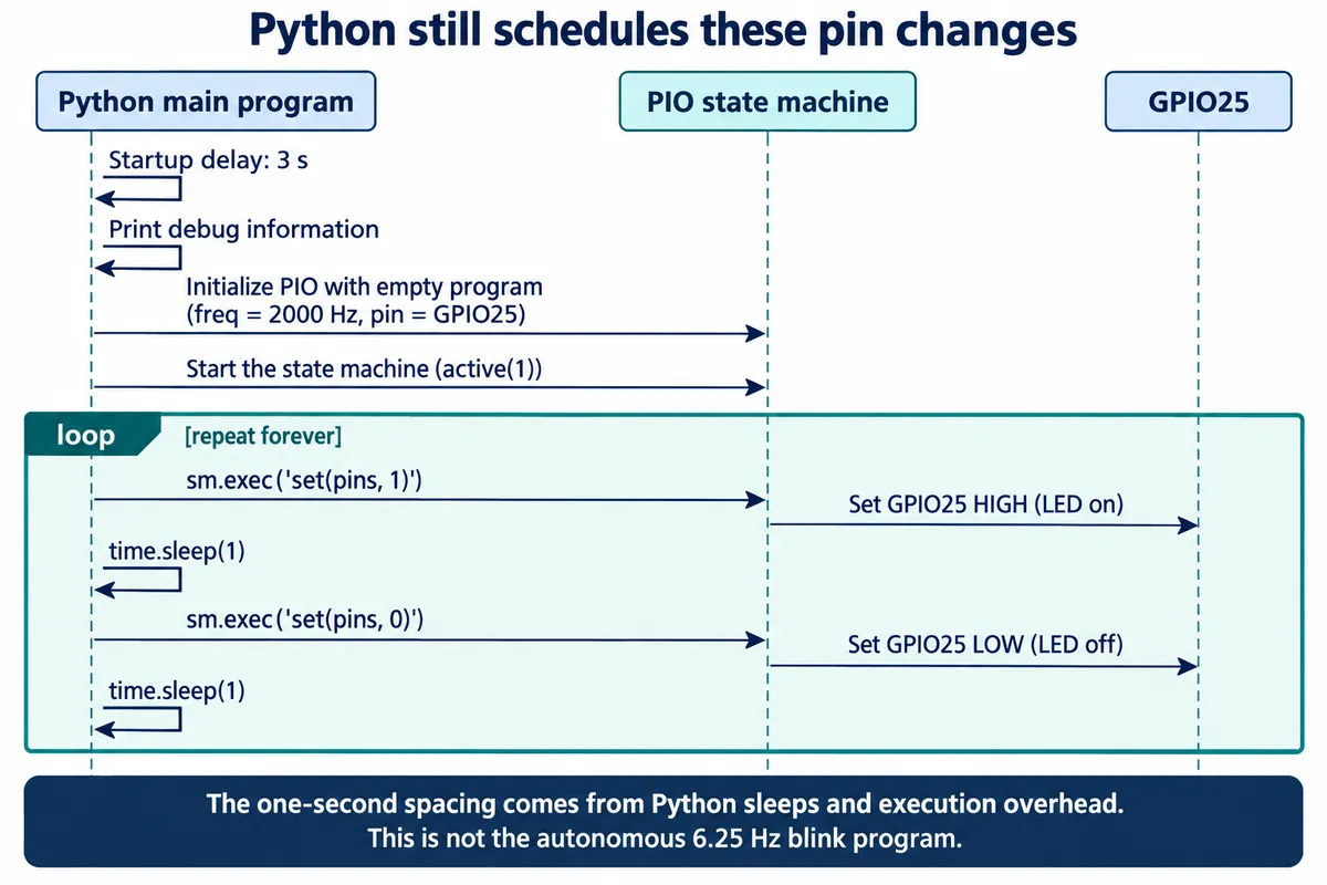
We also ran a comparison. It creates an empty PIO program, then repeatedly asks Python to inject a high-output instruction, sleep for one second, inject a low-output instruction, and sleep again.
sm.exec("set(pins, 1)")
time.sleep(1)
sm.exec("set(pins, 0)")
time.sleep(1)
Here, Python decides when each change happens. The PIO hardware executes the individual commands, but it does not own the interval between them. This can be suitable for an occasional control action. It does not provide the autonomous repeating sequence of the first experiment, and its intended two-second cycle is different from the 6.25 Hz demonstration.
This distinction also helps when reading other people's results. In a June 2023 Arduino-Pico discussion, a developer reported serial timing trouble while writing to flash. It concerns another software stack and a data-fed serial program; it is not proof that a self-contained blink loop fails. It does show why "uses PIO" is too broad a reliability claim. Check what still supplies data or commands from the main application.
Decide what starting and stopping should mean
A prototype needs an agreed idle state as well as a correct running waveform. sm.active(0) stops the state machine; it should not be read as a promise that the pin becomes low or that the final pulse finishes cleanly. The StateMachine reference describes activation separately from injected instructions and pin configuration.
Before connecting this output to another device, decide whether stopping halfway through a pulse is acceptable, what level should remain afterward, and what should happen after reset. Verify those behaviors on the actual board and interface. An LED demonstration cannot establish safe control of a motor, actuator or other load.
The practical result of this experiment is a clearer architecture decision: let a dedicated timing mechanism repeat the sequence, and let the application decide when it is needed. Keep the calculation, the capture and its limits together so the next person can check them.