
A prototype sends a clock or a timed data stream, and the frequency counter shows the number you asked for. Yet the receiving device still behaves inconsistently. If you are integrating an audio interface, a custom display or another timing-sensitive connection, that average may not answer the receiver's question: how long is each high or low pulse?
RP2040 PIO can generate timing without the main program toggling every pin. Its clock divider sets the pace, but a fractional setting reaches that pace by alternating whole system-clock intervals. The average can be correct while the spacing between individual execution opportunities varies.
This note follows the divider mechanism and connects it to a practical decision: whether the chosen clock, PIO program and receiver requirements fit together. The figures are timing models, not oscilloscope captures from a tested product.
Start with the state-machine rate, not the pin frequency
An integer divider of two gives the enabled state machine an execution opportunity every two system-clock cycles. A divider of one gives an opportunity every cycle. Neither tells you that the output pin changes every time: the PIO program decides when that happens, and an instruction can also wait or add delay cycles.
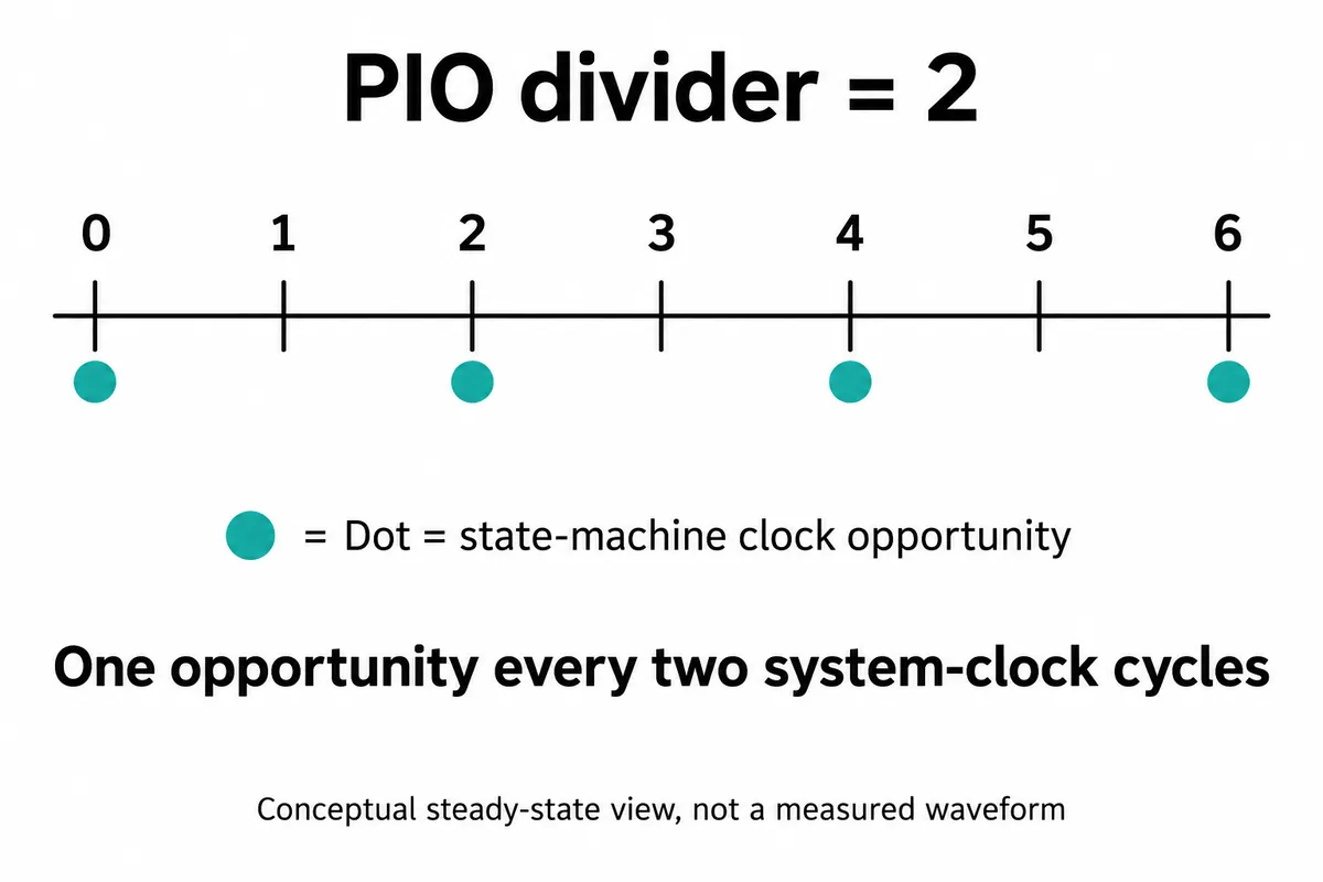
Imagine a repeating program with just one instruction that drives a pin high and one that drives it low, each taking one execution cycle with no stalls or added delays. One output period takes two execution cycles, so a 50 MHz state-machine rate produces a 25 MHz output, not 50 MHz. A different program needs its own cycle count.
That makes the software setting easier to review. In MicroPython, the freq argument to StateMachine sets the execution rate. The official documentation explains that the divider is calculated from the system clock and that rounding can occur. Treat the requested value as a configuration to check, not a measurement at the receiving pin.
A fractional divider describes an average
The divider has an integer field and a fractional field; the stored fractional value counts in 256ths. Take a divider of 2.5 (integer 2, fractional 128). The hardware cannot place an execution opportunity halfway through a system-clock cycle, so it alternates intervals of two and three cycles to reach the average. The RP2040 datasheet's clock-divider section describes this behavior and its possible timing impact.
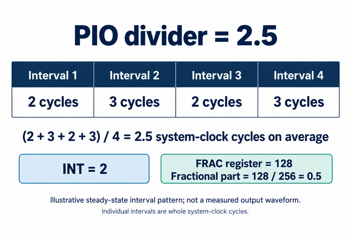
Assume a 125 MHz system clock. One cycle is 8 ns, so two-cycle and three-cycle intervals last 16 ns and 24 ns. Their average is 20 ns, a 50 MHz average execution rate. These are calculated execution intervals, not measured output pulses; where the program places its edges decides how they combine on a GPIO.
In the two-instruction high and low example, alternating 16 ns and 24 ns intervals can add up to a 40 ns period. A frequency counter would show the expected 25 MHz while the high and low durations are unequal. That is how checking only full-period frequency can miss a pulse-width requirement. A longer program or another divider produces a different pattern, so do not carry these numbers over to another interface without counting its instructions.
This is not only a textbook case. A February 2025 Bus Pirate development discussion raised fractional-divider timing while investigating high-rate SPI capture. The thread records a proposed change and a request for a pull request; it does not establish the behavior of every current firmware version. It does connect the divider mechanism to a real acquisition problem.
Choose timing from the receiver's requirements
First find what the receiving device specifies: a minimum high time, minimum low time, data setup time or a permitted clock range. These are different constraints. Write down which one the prototype must meet before deciding that a small variation is harmless or unacceptable.
Then examine the PIO sequence, including delay fields, branches and waits. If the program depends on incoming data, an empty transmit queue can pause it. That is a different mechanism from the repeating interval pattern of a fractional divider, and keeping them apart tells you whether to change the frequency plan, the instruction sequence or the way data reaches PIO.
An integer divider removes this particular source of interval variation. It does not remove every source of clock error, electrical noise or measurement uncertainty. Do not change the system clock casually either, because other peripherals and software may depend on it. Compare feasible clock and program combinations against the real interface requirements, then test the one you pick. As a guide:
- Correct average frequency but unequal short intervals: look at the divider pattern and the instructions between edges.
- Long gaps when the application is busy: look at wait conditions and how data is supplied to PIO.
- A clean unloaded output that fails at the receiver: look at the connection, loading and the waveform at the receiving input.
Capture enough of the waveform to see the pattern
Measure with an instrument and settings suited to the shortest interval of interest. Record high and low durations as well as frequency, and capture enough cycles to expose occasional gaps or repeating variation. A low-rate logic capture adds its own timing uncertainty; a tidy trace on screen does not establish nanosecond accuracy.
Repeat with the intended receiver connected and the rest of the prototype running. Save the PIO code, system-clock setting, divider, instrument settings and captured result together, so someone else can tell a calculated rate from a verified interface.