
A prototype starts a measurement, fills its buffer and shows the result. Press Start again and the readings stop changing, or something elsewhere in the program breaks. Before replacing the board or slowing everything down, check what your data-transfer code leaves behind after the first run.
This matters when a team turns a one-shot demonstration into a tool people use repeatedly: a handheld tester, an interactive display or a recorder that captures a new sample on demand. Those are possible applications of the technique, not products we have demonstrated with it.
On an RP2040 running MicroPython, DMA copies data without the processor executing every individual copy. But starting that hardware again does not mean "repeat the Python setup." Its address registers may now point past the data you intended to use.
Start with the experiment that already works
On our bench, a MicroPython 1.23.0 test created two arrays of 1,024 unsigned 32-bit integers. The source held the values 0 to 1,023; the destination started as zeros. The program configured one DMA channel, started it, printed both arrays and compared the elapsed time with a Python slice copy. The setup is compact:
from rp2 import DMA
from uctypes import addressof
from array import array

source_data = array("I", range(1024))
destination_data = array("I", [0] * len(source_data))
dma = DMA()
ctrl = dma.pack_ctrl(size=2)
dma.config(read=addressof(source_data), write=addressof(destination_data),
           count=len(source_data), ctrl=ctrl, trigger=False)
dma.active(1)
Here size=2 selects a four-byte transfer. The count is 1,024 transfers, so the block is 4,096 bytes. The read and write addresses both increment by default, so the channel moves through the arrays instead of repeatedly accessing their first element. The control word also showed byte swapping disabled.
The test waited with while dma.count > 0: pass, timed the interval with time.ticks_us() and then timed destination_data[:] = source_data[:]. One recorded run showed 104 µs for the DMA interval and 314 µs for the slice copy; a second run gave different numbers. These are observations from a demonstration, not a speed guarantee for a product. Neither run showed that starting the same channel again, without restoring its addresses, is safe.
"Start again" and "start at the beginning" are different
With incrementing addresses, completing this 4,096-byte copy advances both pointers by 4,096 bytes. Those registers describe the next locations to access. Restarting the channel alone can therefore send it beyond the two intended buffers. If the next write damages unrelated data, the failure may not look like a DMA problem at all.
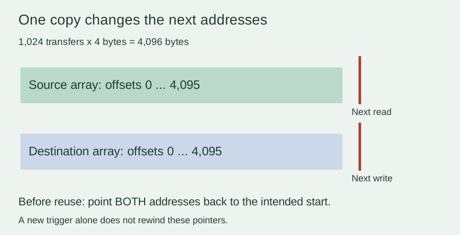
The transfer count behaves differently. On the RP2040, triggering a channel reloads its previously programmed count, so a live count of zero after completion does not mean the next start transfers nothing. The RP2040 register definitions document that reload. The SDK's start operation triggers a channel without resetting its addresses.
The same gap shows up in a November 2022 Raspberry Pi forum discussion. A developer receiving bursts from PIO struggled to refill alternating buffers, and a reply identified the missing write-address reset. The last visible update still reported trouble, so the thread is evidence of a real integration problem, not a verified fix for every capture system.
Check two different copies before adding continuous capture
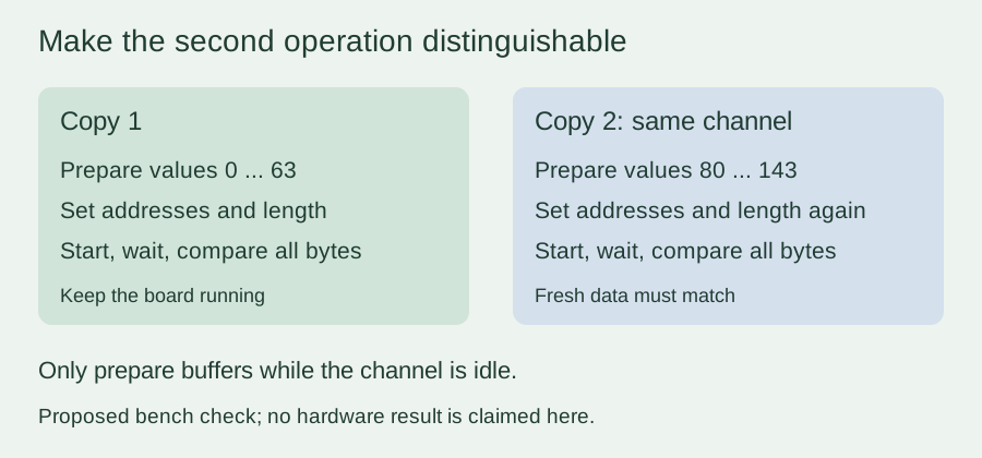
A useful next step is a deliberately simple test: use the same channel twice, but send different data on the second pass. Otherwise an unchanged destination can look correct even when the new operation did nothing.
The check below is proposed; we have not run it on hardware yet. It uses the current MicroPython DMA API and a short byte buffer so the count is easy to inspect. Confirm rp2.DMA exists in your firmware, and run this isolated memory test before adapting it to a peripheral or chained channels.
from rp2 import DMA
from time import ticks_ms, ticks_diff

src = bytearray(64)
dst = bytearray(64)
d = DMA()
try:
    ctrl = d.pack_ctrl(size=0, inc_read=True, inc_write=True)
    for run in range(2):
        for i in range(len(src)):  # change data only while idle
            src[i] = (i + 80 * run) & 0xff
            dst[i] = 0xff
        # Restore BOTH addresses and the length every time.
        d.config(read=src, write=dst, count=len(src),
                 ctrl=ctrl, trigger=True)
        started = ticks_ms()
        while d.active():
            if ticks_diff(ticks_ms(), started) > 1000:
                raise RuntimeError("DMA did not complete")
        if d.unpack_ctrl(d.ctrl)["ahb_err"]:
            raise RuntimeError("DMA bus error")
        if dst != src:
            raise RuntimeError("Copied data does not match")
        print("Copy", run + 1, "matches")
finally:
    d.close()
It waits for each transfer to finish before touching the buffers, and both arrays stay allocated throughout. Supplying the addresses and length on every pass makes each transaction visible in the code, and the finally block releases the channel whether the test passes or raises. The MicroPython DMA reference describes buffer arguments, status and channel cleanup. The polling loop is a diagnostic, not a responsive application design.
Decide what the finished device needs to repeat
If this check passes, you have narrowed the problem: the board can perform repeated, separately configured memory copies. You have not yet tested a display refresh, a sensor's data-ready timing or an uninterrupted audio stream. Add the real peripheral next and check both the first operation and later ones, including what the user sees after Stop and Start.
A continuously arriving stream needs a different design. While one buffer is being processed, new data must have somewhere valid to go. Chained channels or address wrapping can help, but they need their own checks of buffer ownership, alignment and timing. Putting the one-shot example inside a loop does not establish loss-free capture.
For a handoff, ask for a log that identifies each run, verifies its fresh data and records any timeout. That is more useful than a single successful screenshot. When reporting the problem, include the board, the firmware version and the smallest test that reproduces it.