
Your prototype can turn a small motor on and off. Then you unplug the controller, reconnect it, and the motor does something you did not expect. For a team building a battery-powered instrument or a motorized desktop product, this is where "which relay should we use?" becomes a question about what the product should do after an interruption.
A conventional relay and a magnetic latching relay can both switch a load, but they hold their contacts differently. A latching relay can keep its contact position without continuous coil power. That does not mean the finished device preserves the user's last choice: its startup code may immediately send a different command.
On our bench we ran two GraftSense relay modules, an HF46F conventional relay and a G6KU magnetic latching relay, each driving a small motor from an RP2040 controller. The runs show how the switching works and which restart test is still needed before choosing product behavior.
Start with the behavior people expect
Imagine a small motorized display. After a controller crash, should it stay still until someone presses Start, resume its last operation, or keep a switch position while the controller reconnects? Each can be the right requirement for a different product. Write that sentence before selecting the relay.
These distinctions still cause confusion. In an October 2026 Zooz community discussion, a user expected a brief contact closure but saw an output that stayed active. That thread concerned device settings, not a magnetic latching relay, but it is a reminder to separate a momentary command, a maintained output and a physically retained contact position.
Keep experiments like ours at low-voltage motor scale. A component's headline contact rating does not establish that an assembled module suits another load.
Two ways to keep a contact closed
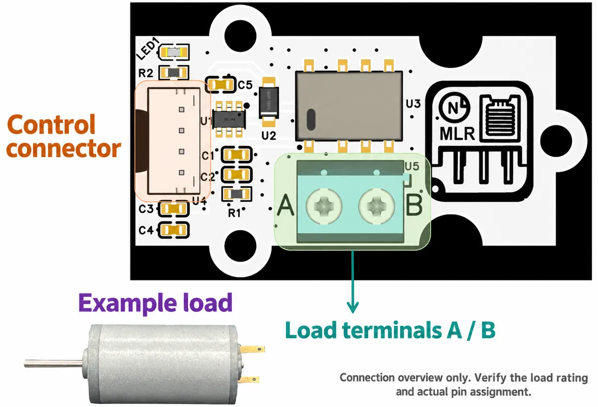
In the HF46F circuit, the controller enables a driver that keeps the relay coil energized: a high control signal closes the contacts and a low signal releases them. The control connector and the load terminals do different jobs. The GPIO sends a command; the contacts switch a separate load circuit.
The G6KU module uses an H-bridge driver that can drive its single coil in either direction. One pulse sets the contact; an opposite pulse resets it. After a successful pulse, coil drive can stop and the contact stays where it is. This is the single-winding latching principle described in Omron's relay FAQ.
For a battery-powered design, that is a possible benefit when a contact must stay in one position for a long time. It also gives the software a new responsibility: it must send the correct pulse and know what it wants the contact to do. Removing coil power is no longer the same command as opening the contact.
The motor experiment
We connected the HF46F module to the controller's DIO1 port with a four-way cable, with GP14 as the control output and GP15 unused. On this control connector, NC means not connected, not a normally closed load contact. The motor had its own 5 V supply path through the relay contacts.
Both runs used our team's relay driver for MicroPython. The test program waited three seconds, created the controller, switched on, waited five seconds, then switched off. So the experiment is one motor start and stop.
The latching run has a gap we need to be direct about. Its program also selected the driver's normal (non-latching) mode, and the wiring left the second control input unused. That is not a complete, verified two-input latching setup. The motor started and stopped, but the run cannot show that the driver delivered the intended set and reset pulses or that the contact held across a power cycle.
To reproduce latching behavior properly, first reconcile the board's two control connections with the driver, then check pulse direction and duration against the relay's datasheet. Switching the mode setting while keeping inconsistent wiring is not a finished test.
The startup code can undo the hardware's memory
In latching mode, the driver produces a 50 ms pulse for on or off, then drives both outputs low. That is the software's chosen pulse length, not something we measured.
More important, creating a latching controller object sends an off command. Even if the relay kept its position through an outage, initialization can change it the moment the software starts.
| What happens | What the driver does | What you still need to observe |
|---|---|---|
| A normal controller is created | Sets its output low | Actual contact and load state during startup |
| A latching controller is created | Sends a reset pulse | Whether the intended contact position is reached |
| A latching "on" pulse finishes | Returns both drive outputs low | Whether the contacts stay set |
| Software asks for the latching state | Returns the last command it sent | Physical contact position and load response |
The last row matters if you plan an "On" indicator in an app. The driver remembers the command it issued; it does not read a contact sensor or measure motor current. A screen can report the intended state without confirming that the mechanism got there. Physical retention and software restoration have to agree.
Read the power readings at the scale they measure
A USB meter on the HF46F setup read about 0.30 W with the relay on and 0.09 W off. On the latching setup it read about 0.09 W, with similar steady readings in both states. These are readings for the whole powered setup the meter sees, not isolated relay-coil power.
They are a reason to look into holding power. They are not a battery-life figure, a switching-energy measurement or a fair comparison under every condition. For your product, measure the complete board in each intended state, then add how often it switches and what the motor draws. A low-power relay cannot make up for a load that dominates the energy budget.
Check the control path before blaming the relay
On the HF46F module, a high input drives transistor Q2, which drives a PC817 optocoupler, which drives the PNP coil transistor. Confirm that polarity on your actual board before integration.
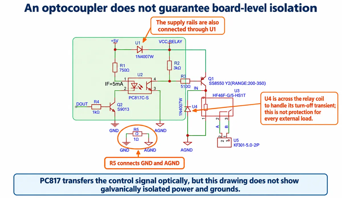
The control ground and the relay-driver ground are linked by R5, marked 1 Ω, and the supply rails connect through U1. So despite the optocoupler, the circuit does not provide galvanic isolation between the two sides. Read the whole circuit rather than inferring behavior from one component's name.
This matters for the restart question because the motor, its supply wiring and the controller form one system. If switching makes the controller reset, changing the relay type alone may not fix the problem. Record supply and reset behavior in the same test as the contacts.
Make the next bench test answer one product question
For the desktop motor example, a useful requirement might be: "After the controller restarts, the motor stays stopped until the user starts it again." For another low-voltage instrument, keeping a routing contact in place might be the goal. Our five-second runs verify neither.
Test the chosen requirement from both starting states. Interrupt only the controller, then only the load supply, then the whole setup. On each restart, record the controller's command, the physical contact or load response, and the state shown to the user. For a latching design, also check what happens if power drops during a set or reset pulse. We have not run these tests yet.
The useful outcome is a small, unambiguous state table that hardware and firmware both follow. Once observed behavior matches it, you can decide whether the latching relay's holding-power benefit is worth the extra control and state-handling work.