
You are preparing a powered display, interactive exhibit or another enclosed prototype for people to try. You can already show a temperature on screen. The next request sounds simple: show a warning when it gets too warm. Before handing it over, you need to see the whole sequence work: warming up, triggering the warning, cooling down and returning to normal.
A developer using a different temperature sensor described exactly this gap in a TI support discussion: the temperature was above the configured limit, yet the expected alert was missing. Later tests showed an alert, but its recovery behavior still differed from what the developer wanted. Reading a value and implementing a useful warning were two separate jobs.
On our bench we connected a GraftSense T117B temperature module to a GraftPort carrier board with a Raspberry Pi Pico, running MicroPython. The module read temperatures without trouble. The output also left an important question open, which makes this a good example of what to check before calling a temperature warning finished.
Start with the actual module and connection
The module connects to the controller's I2C0 connector with a four-wire cable. The program uses GP4 for SDA, GP5 for SCL and a 400 kHz clock. It scans addresses 0x40 through 0x43, and in our run the device answered at 0x40.
That is more useful than assuming an address from a code comment. The chip selects its address through its ADDR pin, and the module has its own address-selection arrangement, so confirm which address responds on your board.
Check power at the module connector as well as at the chip. The module schematic shows a 5 V input feeding a 3.3 V regulator. Confirm the connector supply and the regulated rail on your particular board rather than applying the chip's voltage range directly to the module input.
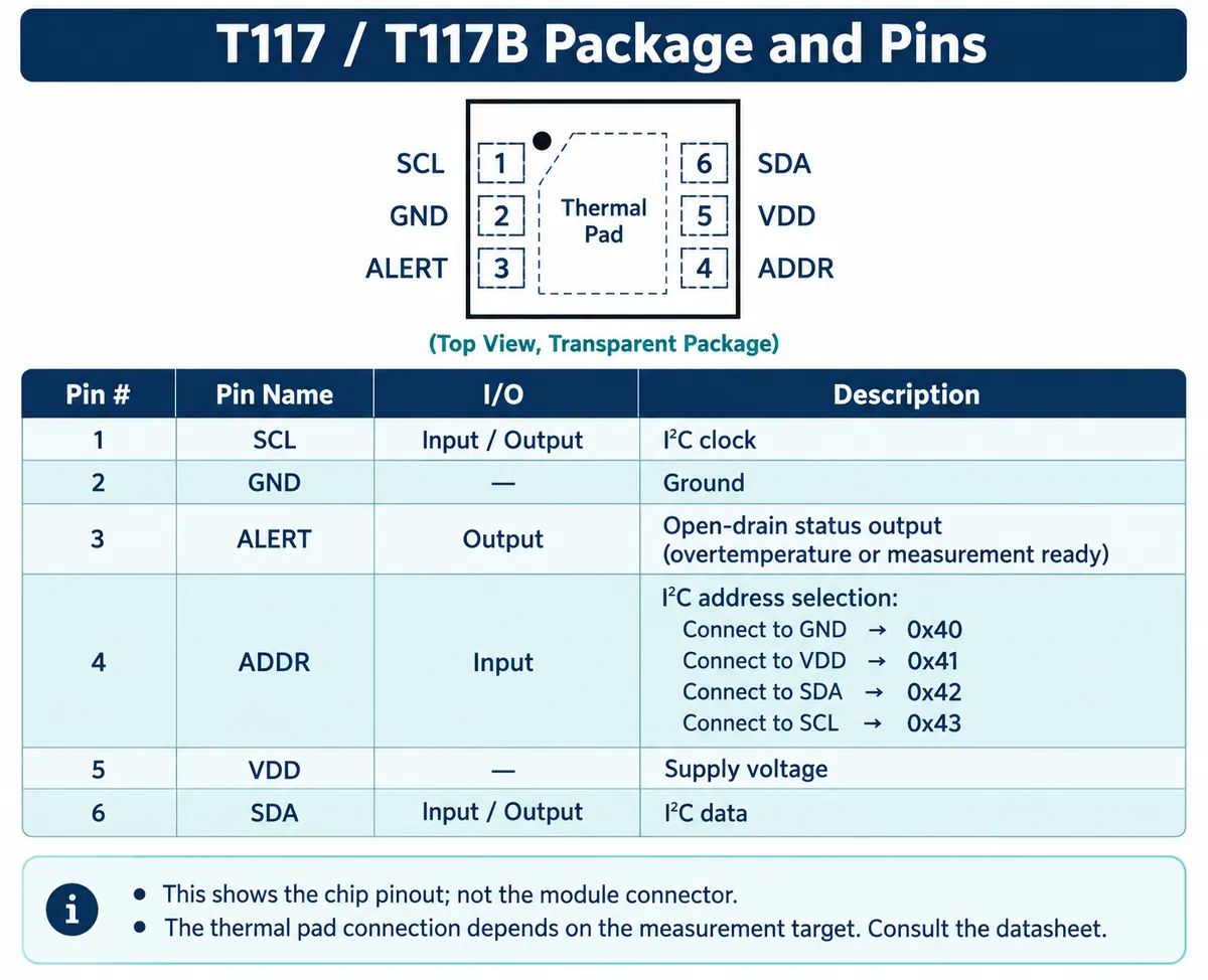
The four connector signals are power, ground, SDA and SCL. They carry the temperature data but do not expose the chip's ALERT output. That matters later if you want a hardware signal to wake the controller or trigger another action.
What the test program did
We used version 1.0.0 of our T117B driver with MicroPython 1.23.0. Keep driver and firmware versions together when you review a result; a different driver can change the configuration and timing.
The program waits three seconds at startup, creates the I2C bus, scans for the sensor and prints four bytes from its ROM-ID area. It then requests continuous measurement with eight-sample averaging. The selected rate setting, MPS_2_1, means one conversion every two seconds, not two fresh measurements per second.
The loop reads the temperature and prints a cached status beside it. The driver reads the low and high temperature bytes, treats them as a signed 16-bit number and converts it:
temperature_c = signed_raw / 256.0 + 25.0
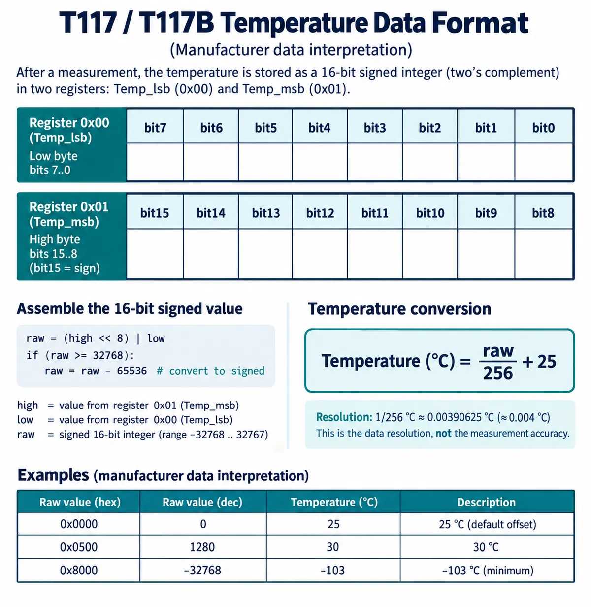
The fine step size should not be confused with accuracy. The Mysentech datasheet specifies the T117B at ±0.5°C over 0 to 60°C. That is a specification for the sensor, not a calibration of the assembled module, and not an assurance that it measures the part of your product you care about.
The loop prints on a nominal 500 ms schedule, and the read call itself waits 500 ms. With conversion configured for every two seconds, repeated values are expected. Faster terminal output does not mean faster sensing or a faster warning.
Read the result before trusting the warning
The test set a high threshold of 30°C and a low threshold of 10°C. It briefly wrote wider thresholds, restored the normal pair and checked that the driver rejected invalid arguments: reversed thresholds, an averaging selection of 99 and a rate selection of 8. Those checks show how the software handles bad requests. They do not take the sensor through the corresponding temperatures or exercise the alarm output.
The recorded temperatures then rose from 29.91°C to 30.58°C. Throughout, the displayed high_alert, low_alert and raw status stayed at zero. It is tempting to call that run complete. But the readings went above the configured 30°C upper limit, and no warning appeared. The test demonstrates communication and changing temperature readings; it does not demonstrate a working high-temperature warning.
There is not enough evidence to name a single cause. Read-and-clear behavior, configuration, conversion timing and the actual pin state need to be checked together, and at no point did an indicator or display change in response to an alarm.
Reading the driver also showed that its mode and polarity bit positions are swapped relative to the datasheet's alert-mode table. With both options left at zero, that alone does not explain this run. It does mean you should reconcile those options before trying a different alarm mode, rather than trusting their names.
Decide where the warning decision lives
Decide whether the program will compare each fresh temperature against a limit, or whether it will rely on the sensor's own alert function. The first approach works over the existing I2C connection. The second requires verifying the chip configuration and, if you want the physical output, getting access to ALERT. Our four-wire connection did not test that path.
Test the warning where the sensor will live
Define what "too warm" means for this prototype before choosing a threshold. A sensor near a regulator, a sensor touching a housing and a sensor meant to measure room air answer different questions. None of them automatically reports the hottest component elsewhere in the product.
A thermostat developer's PCB discussion describes how heat reaching a sensor through the board affected its readings. It is a different project and sensor, but it makes the placement decision concrete. Sensirion's design guide likewise explains why a sensor's own accuracy does not establish the accuracy of the assembled device.
For the next test, record the temperature, the status or decision and the visible warning together. Start below the chosen limit, approach it gradually within the assembly's permitted conditions, then let it cool. Repeat the crossing, and restart the prototype while it is already above the limit. Agree on when a warning should clear; otherwise a feature can pass the first warm-up and surprise you on the second.
Also try a disconnected sensor. A missing reading should have a defined visible state rather than quietly leaving an old temperature on screen. During a user trial, the person testing needs to know whether the device is warm, has recovered or cannot currently measure temperature.
Our bench run covered the first part: a connected module, working data access, parameter checks and recorded output. The next milestone is a repeatable warning-and-recovery demonstration in the intended assembly. That is still prototype validation, not evidence of a certified protective cutoff.