
A prototype can behave perfectly through a ten-minute demonstration and still stop responding when it is left running all afternoon. For an interactive exhibit or a sensor installed away from your desk, the practical question is simple: will someone have to visit it and unplug the power?
A watchdog can be part of the answer. It expects a regular sign that the controller is still doing useful work and requests a reset when that sign stops. Adding a watchdog module is only one step, though. The reset signal has to reach the right hardware, and the application has to return to a useful state after restarting.
On our bench we connected an external supervisor from the DS1232LP family, on a GraftSense carrier, to a Raspberry Pi Pico running MicroPython. We captured its timing with a logic analyzer and deliberately stopped the heartbeat. The result shows why a reset message in a terminal is not yet proof of unattended recovery.
Decide what "working" means
For a display, "working" might mean it accepts input and updates the screen. For a monitoring device, it might mean new readings are acquired and processed. A timer interrupt can keep running while either job is stuck, and if that interrupt feeds the watchdog regardless, the external chip has no reason to reset anything.
Engineers have argued about this for a long time. In a September 2024 embedded-development discussion on Reddit, the author wanted to detect stalled tasks instead of servicing a watchdog from interrupt routines. The question for your prototype is the same: which completed work earns the next heartbeat? MicroPython's watchdog documentation recommends feeding only after checking that operation is correct. The principle holds for an external chip too, even though our driver used a GPIO pin and a timer rather than machine.WDT.
Understand the external supervisor's job
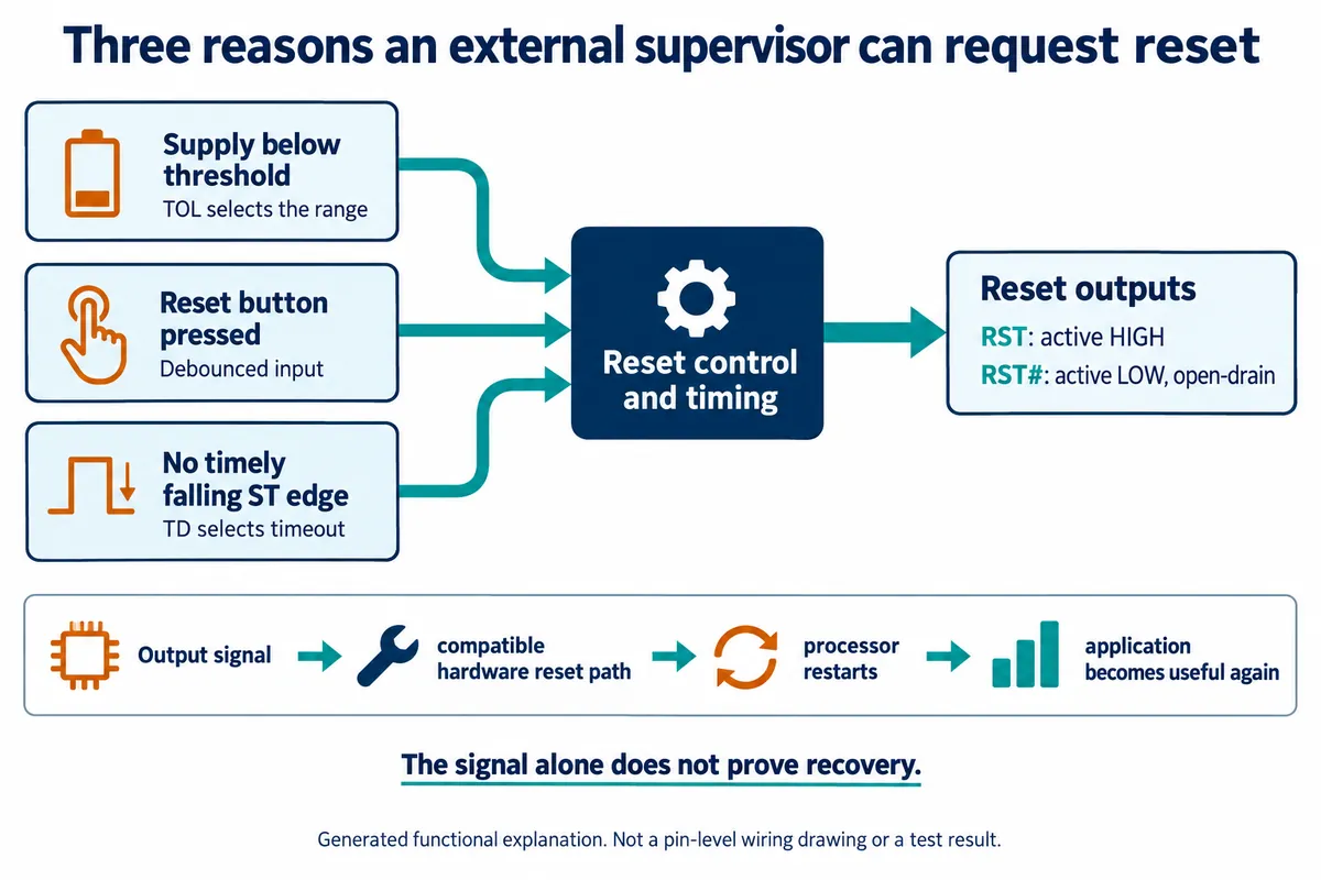
The DS1232LPS-2 on our carrier requests a reset for three reasons: its monitored supply falls out of range, its reset button is pressed, or the expected heartbeat edge does not arrive. It cannot tell whether a sensor reading is meaningful or a user interface is responsive.
Its two reset outputs have opposite polarity. RST is active high; RST# is active low and open-drain, meaning it pulls the line down when active and needs a pull-up when inactive. That decides how it can connect to a controller. The DS1232LP/LPS data sheet describes the behavior and limits. For integration, the key distinction is between generating a reset request and carrying it through a compatible circuit to the processor's reset input. An ordinary input pin that reports an event to software is not the same independent recovery path.
Read the timing before choosing a heartbeat
With no feeding, the logic analyzer showed repeated inactive intervals followed by active-low reset pulses, at three settings of the TD pin. With TD tied to the supply, the inactive interval measured about 1.24 seconds and the low pulse about 0.6 seconds. With TD floating it was roughly 530 ms high and 500 ms low; with TD grounded, about 0.13 seconds high and 0.53 seconds low. Those are observations of one module, not guaranteed values, and they say nothing about how long a full application takes to recover.
The data sheet's table is what to design against. With TD tied to the supply, the timeout is 1.2 seconds typical but only 500 ms minimum (2 seconds maximum). Floating gives 250, 600 and 1000 ms; grounded gives 62.5, 150 and 250 ms. A design that feeds just inside the typical timeout can reset unexpectedly, so leave margin against the minimum, including the application's worst gap between heartbeats.
Our driver had a subtle problem here. Its timer flipped the output on each callback, so with a 300 ms feed interval the pin toggled every 300 ms but produced a falling edge only every 600 ms. The chip responds to falling edges, so that spacing was already longer than the 500 ms minimum before any scheduling delay. The run still worked, but the setting should not be copied as a timing design. Check the real waveform and choose the heartbeat and timeout together. The same applies to a function named kick(): ours flipped the pin once, so not every call produced the falling edge the chip needs.
Follow the deliberate failure test
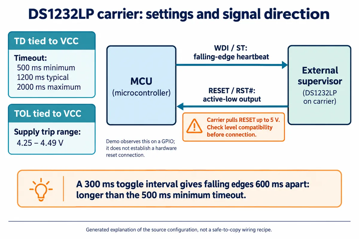
For the application test we tied both TD and TOL to the supply using the carrier's solder pads: TD sets the timeout range and TOL the supply-monitoring range. The program started periodic feeding, printed a running-time message and stopped feeding after ten seconds. A GPIO interrupt watched the reset output. Our program assigned the heartbeat to GP7 and reset observation to GP6, while our wiring table had them reversed; settle that against the actual board before reproducing it.
When feeding stopped, the terminal eventually reported that the reset pin had triggered. A flag made the main loop print "System starting reset..." and exit. The program then stopped its timers and returned to the MicroPython prompt, and further reset-pin callbacks kept appearing. Nothing in that path reset the processor, and the wiring did not connect the supervisor to a hardware reset input. What we demonstrated is timeout detection and a controlled exit from the test loop, not a frozen controller restarting itself.
Pressing the module's reset button while feeding was active also reached the observation code. That verifies another trigger path at demonstration level; a frozen processor could not run that callback.
Give the signal a recovery path
The carrier pulls the active-low reset line up to the module's 5 V supply through 1 kΩ. That is a real compatibility issue for a 3.3 V controller. Do not wire it directly just because it is open-drain. Consider the existing pull-up, the destination input's limits and any interface circuit together, and verify the line on the actual board. Changing a software input setting does not remove a physical 5 V pull-up.
Startup needs the same care. Our program waited three seconds before starting the watchdog. That is convenient on a bench, but an always-active external watchdog wired to the reset input could reset the processor again before it reached that code. A real recovery design must let the application boot and start valid heartbeats without falling into a reset loop.
Then decide what the peripherals do during recovery. Restarting the processor does not restart a separate display, modem or sensor, and it does not guarantee that outputs are harmless during boot. List what must be reinitialized and what users should see while the system comes back.
Test recovery from the user's side
The next trial should stop the useful application work, not just call the driver's stop method. Watch whether heartbeats stop, whether the physical reset input changes and whether the application starts again; each answers a different question. Log enough to tell a watchdog event from a power interruption or a manual restart.
For an exhibit, the final check is whether a visitor can interact again. For a sensor, it is whether fresh readings return with a clear mark of any gap. Measure recovery time with the intended power supply and peripherals connected, and also run legitimately slow operations so the watchdog does not reset a healthy device. We have not run those integration tests yet. One practical note for reuse: the driver we used carries a noncommercial license, so review it before putting it in a product.