
You are building an interactive exhibit. The screen should wake when a visitor approaches, then stay available while they read or try the controls. A small motion sensor looks like a straightforward way to do both jobs. The catch appears when the visitor stops moving: the signal that welcomed them may disappear while they are still using the exhibit.
A PIR sensor can provide a useful wake-up trigger. Deciding that an interaction has finished needs a separate rule. On our bench we tested a GraftSense L916 PIR module with a GraftPort-RP2040 board running MicroPython. This note covers what the board reports, how our example code read it, and what to test before putting it inside a display enclosure.
Decide what "someone is here" means for your product
For an entrance animation, a brief motion event may be enough. For a screen with instructions, switching off as soon as motion stops would interrupt the person you wanted to help. Write the two behaviors down separately before choosing the sensor: what starts the experience, and what allows it to finish?
This is a familiar problem outside exhibits too. In a February 2024 Home Assistant discussion, an office user described combining a PIR with their monitor state to account for nearly motionless video meetings. That is one person's experience, but it raises the right design question: what evidence should keep an interaction active?
For a display, that evidence might include a recent button press or touch. That is a proposed use of the module, not something our test demonstrated. We tested a motion signal; we did not build a finished exhibit or run a room-occupancy study.
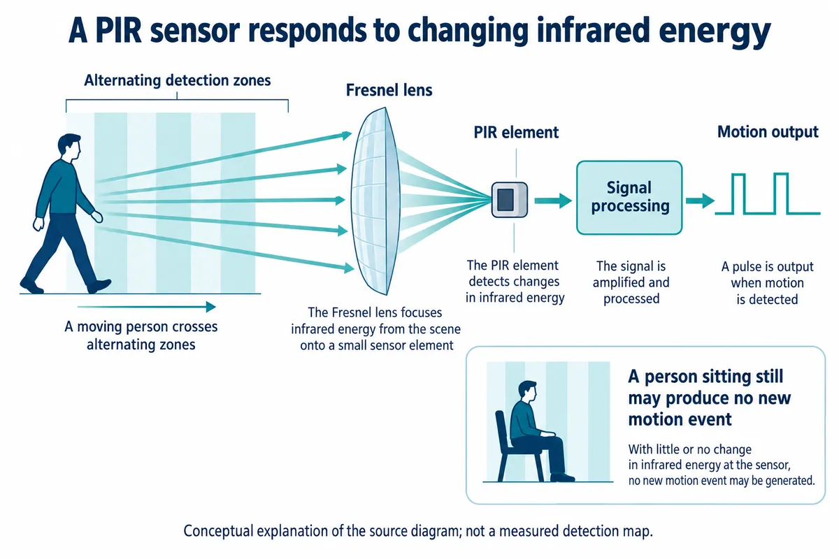
PIR means passive infrared. The sensor receives infrared energy rather than illuminating the room, and changes in that energy produce a detection signal. The signal does not tell the controller who moved, how many visitors arrived, or whether a quiet visitor has left. Panasonic's PIR technical FAQ gives useful background on pyroelectric sensing, although its product specifications do not describe this board.
Start with the actual module and connector
The board carries an L916-labeled sensing circuit, power conditioning and indicator LEDs. Its connector is marked GND, VCC, NC and DIN. DIN is the detection signal going into the controller; NC is unused. Follow the board's function labels instead of assuming every four-pin sensor cable carries the same signals.
The schematic labels the module input rail +5 V and includes a regulator for the sensing circuit. It also has a mismatch between the regulator's part label and its labeled output voltage. Confirm the populated regulator and measure the sensor rail before copying the circuit. The module's input supply and the microcontroller's signal tolerance are separate checks.
We plugged the module into the DIO0 connector on the GraftPort-RP2040, which maps the detection signal to GPIO 6 and the unused contact to GPIO 7. Supply and ground come through the same cable; the two GPIO numbers alone are not a complete wiring instruction.
Reproduce the small experiment before adding product behavior
Our test used our team's PIR driver for MicroPython. It created a sensor object on GPIO 6 with a callback that printed "Motion detected!", paused three seconds after startup, then made a blocking wait for motion with a timeout argument of 20.
That timeout is where the first surprise was. The driver measures the timeout with time.ticks_ms(), so 20 means about 20 milliseconds, not 20 seconds for someone to walk toward the board. A 20-second wait needs 20000 with this implementation. The three-second startup pause is also just an example setting, not a verified stabilization time for every sensor variant. Check the driver version you install before relying on the same behavior.
The terminal on MicroPython v1.23.0 showed a successful blocking-wait message and then several callback messages. The blocking wait checks the current high level, while the callback follows a rising-edge interrupt. Those are two ways of observing the same signal, so the messages should not be counted as separate people or separate visits.
During the test we held the board in our hands and watched an indicator change state. That supports the narrow conclusion that the setup produced a detection response. Because the sensor itself was moving, it says nothing about how reliably a fixed exhibit will detect an approaching visitor, and nothing about range, latency or occupant count.
Give the display its own idea of an active session
For a first integrated prototype, use a motion event to wake the interface. Once a visitor presses a button or touches the screen, let that interaction keep the session active. Return to the idle screen after a suitable period of inactivity, with enough warning or a simple way to continue. The right duration depends on what the visitor is doing; it cannot be read from the sensor's part number.
The sensor may already hold its output high for a while after a trigger. That hardware behavior is separate from the display's session timer.
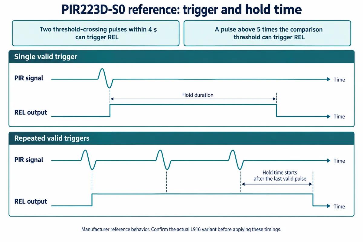
The reference timing comes from PIR223D-S0 material that also uses the L916 name: two threshold-crossing pulses within four seconds, or one pulse above five times the comparison threshold, can trigger the output, and hold time is counted from the last valid pulse. Do not transfer those values to the assembled board without confirming the variant.
If the product must know that someone remains present without interacting, evaluate additional evidence or a different sensing approach. A longer timeout can make a motion-triggered experience less abrupt, but it cannot prove continuous occupancy. For an early exhibit prototype, testing a clear interaction rule is usually more useful than promising invisible, perfect presence detection.
Test again in the enclosure
Mount the sensor in a fixed position and try the paths visitors will actually take: walking across it, approaching from the front, stopping to read, using the controls and leaving. Record both unwanted wake-ups and times when the screen fails to wake. Repeat with the proposed cover fitted, not just the open board.
Visible transparency is not enough to choose a window for a PIR. The same Panasonic FAQ (questions 1-11 and 1-13) explains why ordinary glass blocks the infrared wavelengths its sensors use and discusses suitable cover materials. Treat that as a reason to check the optical path and material with the actual module, not as approval of any transparent enclosure.
The useful milestone is a display that responds appropriately through the whole visit, with its final sensor position and cover in place. Our module test is a starting point for that work: it proves less than a finished occupancy system, but it gives you a concrete signal, connection and software path to build on.