
You already have software that does the job. Perhaps it plays an exhibit video, runs a music session or lets a designer move between views. What feels wrong is reaching for a keyboard every time. A physical button could make the interaction clearer, but building a whole controller before testing one action is an expensive way to find out that the software ignores it.
A useful first prototype sends one deliberate key press, releases it, and checks what the intended application actually does. On our bench we tested the input path with a Raspberry Pi Pico running MicroPython and a WCH CH9328 serial-to-USB-keyboard bridge on a GraftSense carrier. We sent text and keyboard reports to a computer. We did not yet wire physical buttons; that is the next step.
The destination computer belongs in the brief. In a September 2026 discussion about a work-from-home macropad, the starting constraint was using hotkeys without installing software on a managed laptop. That is one person's requirement, and it does not grant permission to work around an organization's device policy, but it shows why the target machine matters.
Start with the action someone wants to perform
For a music team, the action might be starting playback without reaching across an instrument. For an exhibit designer, it might be moving to the next scene. Write the action in plain language first, then check whether the existing software exposes a keyboard shortcut for it and under what conditions it works.
A music-production macropad project shows the appeal: its builder made a small pad and encoder around an existing DAW workflow. That project used different firmware and discusses MIDI. A CH9328 keyboard bridge does not provide MIDI or continuous knob control.
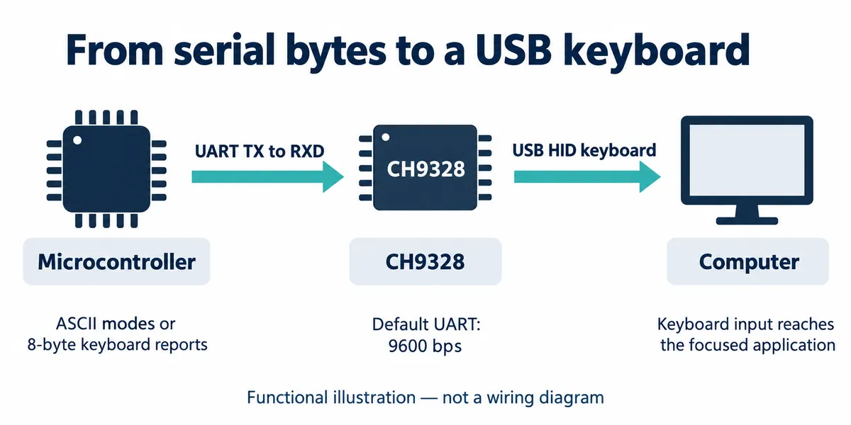
The bridge has a narrow job. The microcontroller sends serial data into the CH9328, and the computer sees a USB keyboard. A successful USB connection does not show that playback started, a scene changed or the right window received the command.
What the hardware connects
A four-wire cable connected the Pico's UART0 to the carrier, and the carrier's USB plug went to the computer. We used 9600 baud with GP16 as transmit and GP17 as receive. The carrier names MTX and MRX from the microcontroller's side, so GP16/MTX leads to the bridge's RXD input. Check that convention before swapping a cable or carrier.
The CH9328 pin description marks TXD as unused in this application. The carrier exposes a receive line, but this is not an acknowledged two-way protocol. Silence on that line does not mean a key command failed, and a transmitted command is not proof that it succeeded.
Power is described at two levels. This carrier has a 5 V to 3.3 V circuit and takes power through USB; follow the matching carrier revision rather than the chip's supply range alone, and never tie two supplies together on that basis. The older manufacturer reference also shows an external crystal, while its notes say chip versions 1.4 and later use an internal oscillator. Not every drawn component is required for every revision.
Choose a mode before sending anything
The CH9328 can interpret visible ASCII characters or accept an eight-byte keyboard report describing pressed keys. Sending the right bytes in the wrong hardware mode produces the wrong result even when the cable and baud rate are correct.
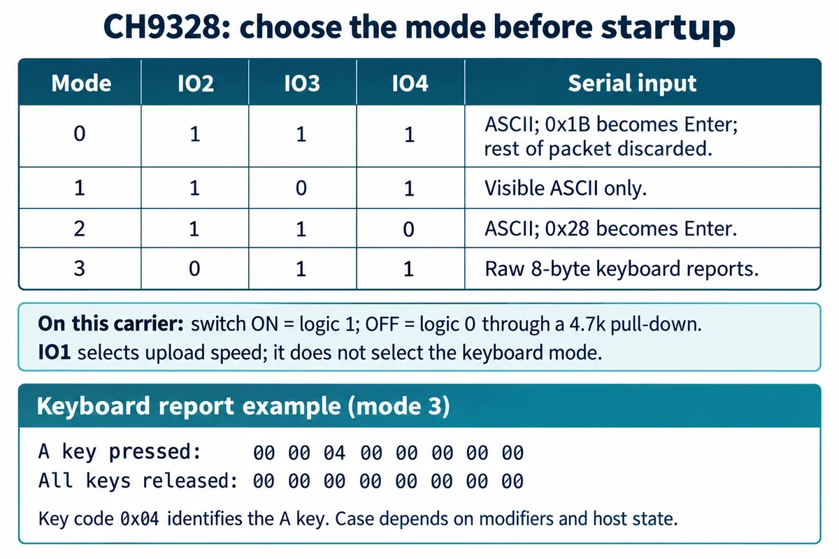
On this carrier, switches set IO2, IO3 and IO4. A closed switch ties the signal to 3.3 V (logic 1); an open switch leaves it pulled down through 4.7 kΩ (logic 0). IO1 selects upload speed and does not choose the keyboard mode. For raw-report mode 3, IO2 is low and IO3 and IO4 are high. Set the switches, then press the reset button so the bridge samples the new levels.
The driver we used has a set_keyboard_mode(3) call, but that only changes how the driver interprets later calls. It does not move the switches or select the chip's mode. Record the physical setting and the program setting together; this distinction can save a long debugging session.
If you are choosing an architecture from scratch, a controller with native USB keyboard support may avoid a separate bridge. A bridge still helps when an existing controller has a spare serial port. Adafruit's CH9328 guide explains the ASCII and raw-report approaches on a different carrier, and the CH9328-Keyboard project is another implementation, whose author reports testing on an ESP8266. Neither gives wiring for this carrier.
Check text entry before building a shortcut
The ASCII modes show the difference clearly on screen. In mode 0 we sent Hello, byte 0x1B to request Enter, then Mode0, and the editor showed two lines. Mode 1 sends visible characters without that conversion, and produced HelloMode1 on one line. Mode 2 uses 0x28 for Enter and gave Hello and Mode2 on separate lines.
Those byte values are mode-specific instructions, not a general Unicode text channel. In mode 0, the manufacturer also specifies that bytes after 0x1B in the same received packet are discarded, so sending a whole multi-line message as one packet is not the same as the sequence we ran.
If your product inserts text, test the actual punctuation and keyboard layout you plan to use. The driver's text function applied Shift only for uppercase letters and did not use its own list of shifted symbols, so characters such as ! need attention. A clean Hello does not cover every symbol, accented character or language.
A key press needs a release
Mode 3 gives the controller direct control. An eight-byte report holds a modifier byte, a reserved byte and six key-code positions. 00 00 04 00 00 00 00 00 reports the A key pressed with no modifier; eight zero bytes release all keys. A modifier of 02 means left Shift, though the displayed character still depends on the host's layout and state.
Our mode 3 test cycled through ordinary key codes and then modifiers in a keyboard-test utility, and the keys registered. That is evidence for that programmed sequence on one computer, not for timing accuracy, compatibility with every application or a physical switch. For your own first test, one harmless key in an empty text editor is easier to judge: did it arrive once, repeat or stay held?
This press-and-release sequence uses plain UART writes, assuming the carrier is already switched to mode 3 and restarted. It illustrates the sequence; it is not a button-scanning program.
from machine import UART, Pin
import time

uart = UART(0, baudrate=9600, tx=Pin(16), rx=Pin(17))
time.sleep(3)  # time to focus an empty test editor
uart.write(bytes([0, 0, 0x04, 0, 0, 0, 0, 0]))
time.sleep_ms(50)
uart.write(bytes(8))  # release all keys
Turn the test into one useful physical control
Once one press and release behaves correctly, connect the physical input you intend to use. A push button needs a rule for what counts as one press, including how to handle contact bounce. A held button needs defined behavior: repeat, stay held or trigger once. Those are interaction decisions, not only circuit details.
Then try the action in the destination application: with the expected window focused, with another window selected, and after unplugging and reconnecting the controller. Keyboard events follow the computer's focus rules. If the action must work regardless of focus, look at the application's own control interface rather than more elaborate key sequences.
Keep the first physical arrangement adjustable. Put the button where a musician, presenter or visitor will actually reach it, and see whether its label and feedback make the result clear. A light confirming that the microcontroller sent a report is not confirmation that the application acted. If that matters, the next prototype needs a feedback path.
That gives you a brief for the enclosure and later build: the intended action, the target computer and software, the input behavior, the connection, and evidence that the action works. Button placement, strain relief and connector access can then be designed around an interaction you have tried. Production reliability and certification are still separate work.