
A wheel turning in your hand is a satisfying first result. The next one is harder: the motor must start while carrying the product, move at a useful speed, and stop when asked. A percentage in the software helps control that movement, but it cannot tell you how much work the motor is actually doing.
This matters when a small team adds motion to a display, a feeder or a simple wheeled prototype. "Run at 25%" sounds like a speed setting. In a basic PWM program it usually means switching power on for a quarter of each cycle. The load still helps decide what happens at the shaft.
On our bench we switched a small motor with a wheel through a GraftSense MOS motor-switch module and recorded it turning and stopping. That is a useful starting point for deciding what to measure before attaching the rest of a mechanism. It is not a speed-control or load-capacity test.
What the bench run establishes
The setup was a GraftPort-RP2040 controller, a single MOS switching module and a motor with a wheel. GP6 provided the control signal through the DIO0 connector; GP7 was unused. The module's VIN terminals take the motor supply and VOUT connects to the load. We did not establish a tested supply-voltage and current range for this assembly.
The program created a 1 kHz PWM signal and passed it to our team's MicroPython driver for the module. At 1 kHz one switching cycle lasts a millisecond. Duty cycle is the proportion of that cycle commanded on; the driver accepts a raw value up to 65535 or a percentage.
The test program first tried several values, including some outside the allowed range. It then left the output fully on for five seconds, off for ten seconds, tried an inverted-output example on a different pin, and released the PWM objects. The wheel started, turned and stopped.
The terminal output is useful for checking software behavior. A raw request of 70000 was clipped to 65535, and 150% was clipped to 100%. But the 25% step had no settling delay before the next setting replaced it, so the run tells us nothing about the wheel's steady speed at 25%.
The driver's status call reads back its stored duty setting. There is no shaft sensor, current measurement or flow measurement behind it. Its printed "percent" is not a percentage of measured speed, torque or useful output. In inverted mode it reports the electrical duty after inversion, another reason to label logs carefully.
Choose a measurement that matches the job
For a moving display, the useful observation might be how long a rotation takes. For a feeder, it might be how consistently material is delivered. For a wheeled prototype, it might be whether it starts on the intended surface with the intended load. Our run tested only a wheel on the bench.
The gap between a setting and a result shows up in real builds. In an ArduinoProjects pump discussion, a builder of an automatic refilling station reported that the pump hummed below a certain setting instead of starting. That is a different motor and module, so its threshold is not a number to copy. It is a good reason to test starting separately from running.
Once the electrical setup has been checked for your motor, record a small set of observations:
- the command;
- whether the motor starts from rest;
- the output after it settles;
- supply behavior;
- any heating.
Repeat under the intended load. A motor that keeps turning after you lower the command may still fail to restart at that same setting.
Starting and a blocked shaft can draw much more current than free running. Use the motor's documented characteristics when choosing a supply and driver, then verify the intended operating conditions. Pololu's motor and supply selection guide explains why stall current and current limiting matter; its controller ratings do not apply to this module.
Check the circuit before scaling up
The module's schematic matters for deciding what can be reused. There is an optocoupler on the control input, but R4 connects the two labeled ground networks with zero ohms. As drawn, the circuit does not provide galvanic separation between those grounds, despite the module's name.
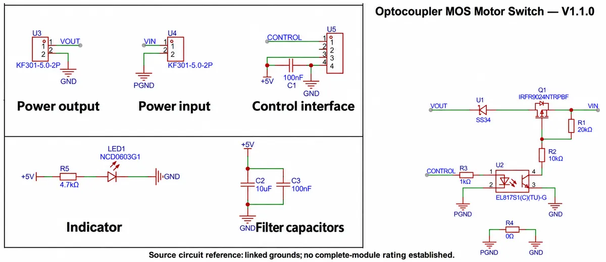
A second detail to catch before changing the load: the SS34 diode sits in series with the output path. It is not a flyback diode across the motor. The drawing does not show motor turn-off protection. Have the actual turn-off current path and voltage transients checked before using the design with a new inductive load.
The 55 V and 6.8 A figures quoted for this module are not verified module ratings either. A MOSFET's limits depend on conditions and are different from the limits of its gate drive, diode, connectors and board cooling. The IRFR9024N datasheet is a component reference; it does not qualify the whole assembly at those numbers.
None of this erases the recorded movement. It sets the next step: keep the bench run as evidence of switching, then choose or review the power stage for the real mechanism. Raising the PWM frequency or changing a software percentage does not substitute for that work, and a higher frequency changes what the whole switching path has to handle.
Decide whether simple control is enough
If the product only needs a brief, repeatable movement and testing shows enough margin, a simple timed command may be sufficient. If speed or delivered quantity must stay consistent as the load changes, measure that output and consider feedback. If it needs reversal or controlled braking, choose a power stage that provides them; a single-switch module like this one does not.
You can make that decision with a small, specific test instead of redesigning everything at once. Define the job, observe starts and stops under the real load, and keep the command separate from the measured result. The result tells you whether to adjust the mechanism, the supply, the driver or the control strategy.