
You can make a sensor value change when someone tilts a handheld object. The harder part is making that movement feel like a dependable control: a musical effect should stop changing when the performer stops, and an interactive prop should recognize the same gesture the next time it is picked up.
That is a good first question for a design or music team building a motion-controlled prototype. Do you need to recognize a brief twist, measure a tilt, or keep pointing in the same direction for several minutes? The three can look alike in a demo, but they ask different things of the sensor and the software.
On our bench we connected a GraftSense MPU6050 six-axis module to a GraftPort carrier with a Raspberry Pi Pico W, read acceleration and rotation in MicroPython, and plotted filtered angle estimates beside integrated gyroscope values. This note covers what that showed and what it did not.
Start with the gesture the person will make
A real example of the problem appeared in an Arduino forum discussion from December 2019. A maker had put an MPU6050 into a guitar to control a digital audio workstation over MIDI, but saw values drift while the instrument was still. That report does not explain every drift problem. It does show why "the numbers change" is a poor acceptance test for an interaction.
For a short twist that changes an effect, rotation rate may be enough: the software reacts to how quickly the object turns and stops when the rate returns close to its resting value. For a control based on holding an object at an angle, an estimated tilt is more relevant. A pointer that must keep a long-term direction needs another reference; the MPU6050 has no compass.
A gyroscope measures angular rate. Adding that rate over time estimates how far something has turned, but a small resting offset accumulates into an angle error. The accelerometer gives a different clue: when the object is fairly still, gravity indicates tilt. During a vigorous gesture it also senses the gesture's own acceleration. Analog Devices' inclination-sensing note explains both the gyro error buildup and the gravity assumption behind accelerometer tilt.
So smoothing a trace and establishing its accuracy are separate jobs. The prototype needs a repeatable physical movement to compare against, not just a filter with a reassuring name.
Recreate the signal path before changing the interaction
The module carries a ZY-MPU6050 sensor board on a carrier with a four-pin GND, VCC, SDA and SCL connection. In our code the sensor uses software I2C on GP4 (SDA) and GP5 (SCL) at 100 kHz, and the program scans for a device at 0x68 or 0x69 before creating the driver object. A separate UART on GP8 and GP9 sends values to the computer for plotting; it is not the interface that reads the sensor.
Check power at the module level as well as the chip level. The carrier accepts 5 V, while the MPU-6000/MPU-6050 datasheet gives the bare sensor a much lower supply range. A regulator on the module does not make every signal pin 5 V tolerant. Before adapting this assembly, confirm the module supply and the I2C pull-up voltage against your host board.
Read the raw motion before asking for an angle
Our driver reads acceleration, angular rate and the chip's temperature channel as separate calls. Acceleration can be returned in meters per second squared or in g, and angular rate in degrees per second. Keep the units explicit when deciding whether the object is resting or moving; one numeric threshold cannot serve both acceleration formats.
Our console reads showed the connection and conversion path producing values. They do not establish angle accuracy, a minimum recognizable gesture or the behavior of an enclosed handheld device. The temperature channel read about 24.72°C; that is the chip's internal reading, useful context when resting behavior changes, not a calibrated room temperature.
For an interaction prototype, record what happens when you turn one intended axis at a time and then set the assembly down. Mark the board's orientation relative to the grip so that "tilt left" has one meaning. A board mounted sideways inside the case needs an explicit axis mapping; renaming a variable from x to roll is not that mapping.
What the angle comparison shows
The test program kept two integrated gyroscope angles, requested two filtered angles from a complementary filter, and sent four comma-separated values to the computer: gyroscope roll, filtered roll, gyroscope pitch and filtered pitch. The terminal also showed elapsed time, temperature and the raw readings.
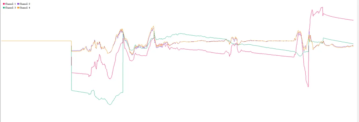
Some traces move away from their earlier levels, while others stay closer together or come back. There was no independent angle reference or labeled movement timeline, so the plot cannot tell you the filter's accuracy. Calling the smoother curve "correct" would go beyond the evidence.
Reviewing the code turned up a specific issue: roll and pitch updates share one filter state and one previous timestamp. In an offline check with the same filter class, two updates at the same mocked millisecond returned the same angle even though the synthetic roll and pitch inputs differed. That is a software finding, not a hardware measurement. Before relying on two estimated angles, give each axis its own state, use a consistent sample interval, and validate against known orientations.
One more qualification: the main loop periodically resets its integrated gyro angles to the filtered values. The trace labeled "gyroscope" is therefore not an uninterrupted gyro-only reference for the whole run. The acquisition and plotting work still stands; this changes what you can conclude from the comparison.
Make the next test match the way the controller will be used
Pick a short set of repeatable actions: hold still, turn one axis, return to the starting position, hold still again. Keep the raw values as well as the output the interaction uses. If a control keeps moving after the hand stops, the raw recording helps separate a sensor offset, a software-state error and an over-sensitive mapping.
Timing belongs in that recording. The loop sleeps 50 milliseconds, but the driver also waits during sensor reads, and printing and serial output take time, so it is not a 20 Hz loop. In the excerpt we captured, terminal timestamps advanced by roughly 80 milliseconds. Use measured elapsed time when integrating rate, and test with the display, communications and other application work running.
The topic remains active in research. A single-axis RP2040 and MPU6050 preprint revised in October 2026 examines combining accelerometer and gyro measurements. It is separate work; its abstract does not justify transferring an accuracy claim to this assembly.
For a first user test, turn the signal into one deliberate action. A twist could change a value only while an enable button is held; a tilt could select among a few broad regions with a neutral zone between them. These are candidate designs to try, not guaranteed solutions. They let the team learn whether people can control the result before asking the sensor for precise continuous orientation.
If the concept needs a persistent pointing direction or position in space, state that requirement now; a six-axis trace alone does not meet it. Our setup gives a readable route from module to raw data and a useful angle comparison. The next milestone is an interaction that still behaves correctly after repeated movement and a return to rest.