
You want a tray that knows whether an item has been added, a container that reports how much is left, or a simple device that counts identical objects by weight. Connecting a load cell and getting a number on screen is a promising start. The harder question is whether that number stays useful when someone moves the object, leaves it there or switches the device off.
On our bench we built a small weighing platform with a bar load cell, a GraftSense HX711 module and a GraftPort-RP2040 board running MicroPython, calibrated it and tested it with known weights. This note covers what worked and what still needs checking before such a platform becomes part of a product.
For a first prototype, choose one decision the weight must support. Detecting an empty tray tolerates more variation than dispensing a small portion, and the decision should set the test, not the decimal places the program prints.
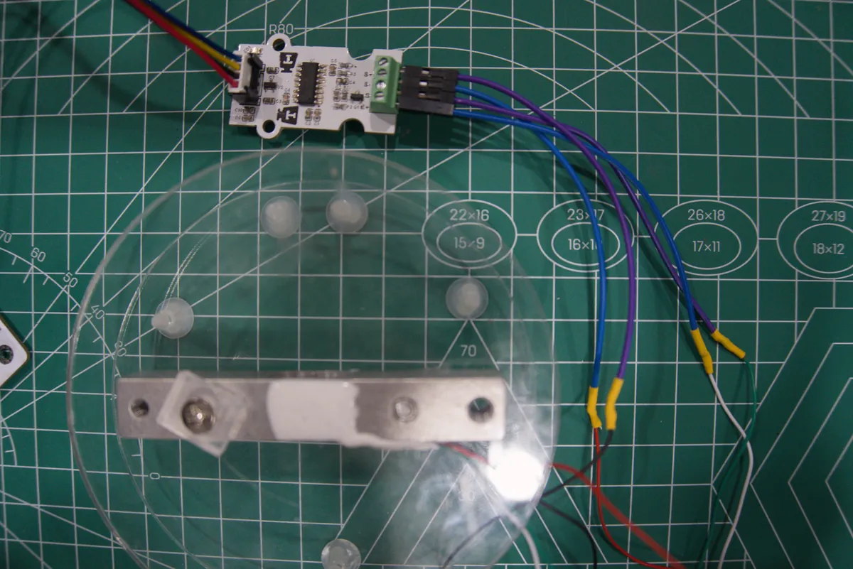
The mounting is part of the sensor
The metal bar is the load cell. Applied force deforms it very slightly, which changes the resistance of strain gauges bonded to it. Their bridge circuit produces a small differential voltage. The HX711 amplifies and converts that signal into a digital count; it does not measure grams directly.
So the object needs a predictable path through the platform into the load cell. If the tray touches the enclosure or a cable pulls on the moving part, some of the force takes another path, and a calibration number cannot fix a tray that rubs differently every time it moves.
For a bar-style cell, SparkFun's HX711 breakout hookup guide shows one end fixed to the base and the other to the platform, with clearance for the intended deformation. Follow the mounting specification for your actual cell; a support suitable for a bar is not automatically suitable for a button or S-type cell. We kept the platform open so we could see if a screw, spacer or cable had moved.
Connect by function, then check the software pins
The module labels its load-cell terminals S+, S-, G and E+. They are not four interchangeable wires.
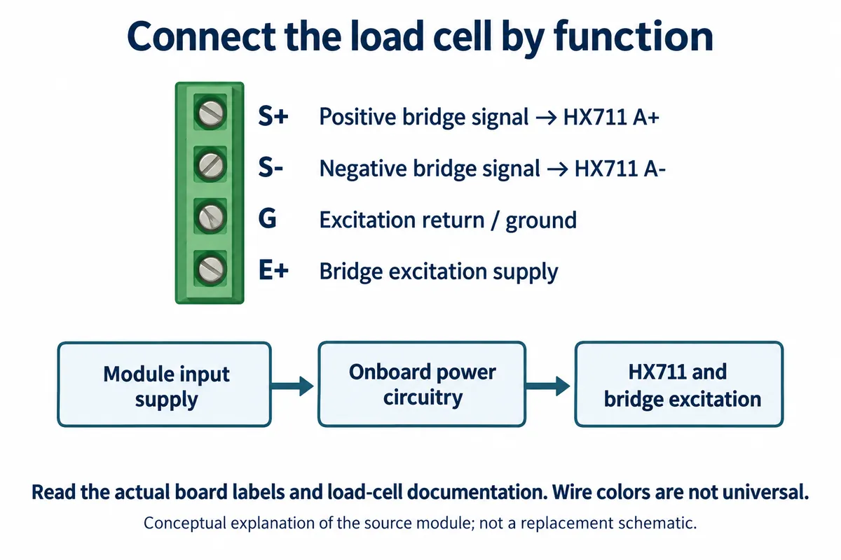
Color-to-terminal tables differ between load cells and suppliers, which is why copying a color list is risky. Identify the excitation and signal pairs from the load-cell documentation and the module labels.
On the controller side, the HX711 uses a data output and a clock input. Despite the similar connector, it is not an I2C device, and an I2C scan will not find it. The data line signals when a conversion is ready; clock pulses then shift out the result and select the next channel and gain.
Confirm from your board's connector routing which controller pin carries DATA and which carries SCK, and make every version of the program match it. Also check the module's logic supply against the host: the schematic shows a 3.3 V digital rail and an analog regulator, which does not make it 5 V-signal compatible.
Clear the empty platform, then calibrate
The first step is tare: tell the program what the empty platform looks like. Leave it in its intended position with nothing on it, let it settle, and average several readings. That average becomes the zero offset. Our program averaged 20 readings and recorded an offset of 210089.7 counts. A large raw count on an empty scale is normal.
Next we placed a weight marked 100 g, averaged again and divided the increase by 100. The run reported a net increase of 37941.14 counts, giving 379.4114 counts per gram. That factor belongs to this assembled sensor and this calibration run; copying it into another device would not calibrate it. Our program also rejected a calibration if the increase was under 1000 counts, a guard for this setup rather than a universal limit.
For the driver layer we used the MicroPython HX711 driver by robert-hh (MIT), with our own calibration program on top. Choose a calibration mass suited to the cell and to the part of its range you plan to use.
Check with a weight you did not calibrate with
After calibration the 100 g weight read about 100.04 to 100.12 g. That is encouraging, but that weight had just set the conversion factor. The more useful check was a separate 50 g weight.
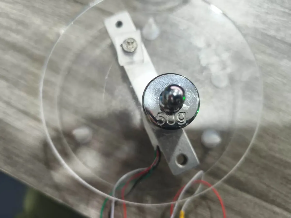
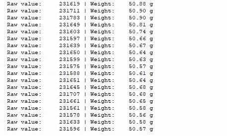
It read about 50.56 to 50.90 g. That difference matters if your application needs sub-gram decisions. These readings cannot separate the reference weight (which had no calibration certificate), mounting, calibration, drift or filtering, and they were not repeated trials. They are a concrete result to investigate, not proof of accuracy.
A phone on the platform read about 162.07 to 162.21 g, which shows an ordinary object giving a plausible result. A phone is not a reference mass, so that proves nothing about accuracy.
The program printed a raw reading and then called a function that takes another reading through a low-pass filter. The raw and gram values on one line are therefore not the same sample. Filtering steadies the display, but it also makes a newly changed load take time to settle. Record the sampling and filtering settings when you compare results.
Make the software survive a real interaction
A bench script can stop for an Enter key during calibration. A user-facing tray needs a clear way to enter calibration, confirm the platform is empty, apply the reference weight and save the result. It also needs a startup policy: taring automatically with an object already on the tray would hide that object's weight.
Check how your read routine handles a conversion that is already waiting. An interrupt-based read that only waits for a new falling edge, even when DOUT is already low, can leave a ready conversion unread during a pause for the user, and a later call then times out waiting for an edge that already happened. The read should accept the ready-low state and handle timeouts explicitly. In the HX711 datasheet timing, 24 clocks shift out data and extra clocks select the next gain, and holding the clock high too long puts the chip into power-down.
A failed read should produce a clear "unavailable" state, not an apparently valid old weight. Save the calibration factor together with the hardware setup it belongs to, and provide a deliberate recalibration path after any load-cell or mounting change.
Judge it against your tray's job
The next step is a short, repeatable test on the intended platform. Place the same known load in the center several times, remove it and check the return to zero. Try the permitted positions near the edges. Leave a fixed load in place for as long as a normal use session and see whether the reading moves. For an item counter, weigh several real items individually too; their natural variation can matter as much as the electronics.
Match the evidence to the decision:
- Has an object been placed? Measure empty and loaded ranges, including ordinary movement and off-center placement.
- How much remains? Check repeatability at several loads and drift over the holding time.
- How many similar objects? Measure variation between real objects and count errors near the decision boundaries.
- Can it go in an enclosure? Check clearance, cable forces and repeatability after assembly.
Other builders hit the same wall: a March 2024 DroneBot Workshop feasibility study of a weight-based item counter reported that an oversized load cell and crude mounting left drift as an open risk.
Our platform reached a worthwhile milestone: a visible calibration process and results at more than one load. The next milestone is showing that it makes the right decision repeatedly in its intended mounting and use. A load-cell specification, mounting photos, the required weight range and a log of repeated measurements are what show whether the next work belongs in the mechanics, electronics, firmware or calibration.