
A small educational robot follows a strip of tape during a desk test, then loses it after you fit the sensor under the chassis. It is tempting to rewrite the steering code first. But moving the sensor changes the light it receives, and a threshold that worked in your hand may no longer separate the track from the floor.
That makes mounting part of the sensing system. In an April 2026 discussion about a TCRT5000 array, a builder could only distinguish the line when the sensor came very close to it, and later reported success after changing the angle. That is an example of a physical change affecting detection, not a universal instruction to tilt every sensor.
On our bench we looked at this first step with a single-channel GraftSense reflective sensor module wired to a GraftPort-RP2040 controller. We adjusted the switching threshold and recorded digital transitions while moving the module by hand across a dark strip. There was no motorized chassis in this test.
What the module can actually see
The sensing part is a TCRT5000L: an infrared emitter beside a phototransistor. Light leaves the emitter, reflects from the nearby surface and reaches the detector. An LM393 comparator on the carrier compares that signal with an adjustable reference and turns it into a high or low digital output.
This is a reflection measurement with a threshold, not a camera identifying black objects. The track material, its background and the gap below the sensor all affect the contrast available to that threshold. Test the exact tape or printed surface you plan to use, rather than assuming anything that looks black behaves the same.
The Vishay datasheet gives a peak operating distance of 2.5 mm. Its wider 0.2 to 15 mm figure describes a relative-output condition, not guaranteed black-line detection over that range. A sensible starting point is a close, controlled gap, followed by tests on your actual surface and mounting tolerances. If you plan several sensors at one mounting height, check that every installed sensor separates the two surfaces consistently, not just one.
Reproduce the single-channel connection
We connected the module to the controller's DIO0 port with a four-wire HY2.0 cable. GP6 read the digital signal; the second signal position was unused. The carrier labels the signal DIN from the controller's point of view, while the schematic calls the module's output DOUT.
Use the connector mapping for the actual carrier. This board has a regulated internal supply and a pull-up on the comparator output; that is not a reason to connect an arbitrary 5 V module straight to an RP2040 input. Verify the output voltage whenever you substitute another board.
This setup does not read analog reflectance. Once the comparator reduces the optical signal to one bit, the program knows which side of the threshold it is on, not how far the sensor is from the line's center. That matters later, when you choose between a simple edge-following demonstration and an array for steering.
Adjust R5 at the height you will use
R5 is the 10 kΩ potentiometer that sets the comparator's reference.
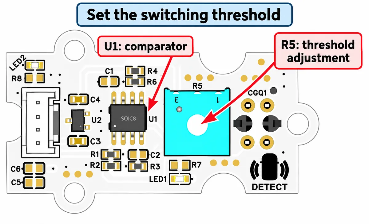
Our calibration sequence went from a light background, to the dark line, then slowly across the boundary between them. Do those three checks at a fixed gap. Turn R5 until the output clearly distinguishes the two surfaces, then repeat the crossing without changing the module's angle or height.
Read the GPIO value as well as watching the indicator LED. Our notes disagreed about whether the LED should be on over the black line, and the code comments labeled black as 0 without a synchronized record of surface and reading. Establish the actual 0/1 mapping on your board instead of trusting an assumed LED rule.
If raising the sensor slightly makes both surfaces produce the same value, the threshold has too little separation for that mounting. Adjust the physical position and retest. Inverting the logic in software swaps the meaning of 0 and 1; it cannot restore contrast the optics have lost.
Watch the transitions before connecting them to motion
We used our team's MicroPython driver for this module. The test program created the sensor on pin 6, registered a callback, printed the current reading once per second, and released the event handler on interruption.
That program makes two different observations. The regular read reports the state at the instant it is sampled. The callback reports a change between states. The driver watches both rising and falling edges and uses micropython.schedule to run the user callback outside the interrupt handler itself. In our test the callback only printed the new value; it did not steer a motor.
The terminal showed repeated 0 and 1 readings with callback messages between them. That demonstrates a changing digital input. It does not measure position along a track, maximum speed or missed transitions, and a one-second status print is not a suitable rate for a robot's steering loop.
One more detail: we moved the module over a dark strip on a blue work mat, not over the white paper our written calibration steps assumed. Keep that kind of difference in mind when you pick the materials for your own test.
Give the mechanical design a testable requirement
Before fixing the sensor bracket, record the height and angle at which both surfaces produce stable, distinct states. Repeat with the chassis at its expected clearances and under the lighting where the robot will run. Keep the motors stopped during this first characterization so motion does not hide a simple detection problem.
Then move the assembled prototype slowly across the boundary and look for repeated unwanted transitions or stretches where the line disappears. A single digital channel tells you a boundary was crossed; steering through bends and recovering a lost line may need more information. Choose the sensor arrangement and control method from those requirements, not from one LED switching on the bench.
For a workshop kit or a repeatable exhibition piece, a defined mounting position and a clear calibration routine can matter as much as the code. They let someone who did not build the first prototype reproduce the result.