
A small mechanism can move convincingly in a demo and still be confused after a restart. A plotter, moving display or motorized prop needs a known starting position before "move ten millimeters" means anything useful.
A limit switch can provide one physical reference. The first step is modest: establish that the controller correctly recognizes the switch being operated. On our bench we ran that input test with a GraftSense limit-switch module on a GraftPort-Pico controller running MicroPython. The test had no motor, no homing routine and no measurement of positioning accuracy; this note covers what it showed and what comes next.
Confirm the input before asking it to control motion
In a recent Arduino community question, a builder found that a CNC controller reported its Z limit as continuously active even after changing the switch. The author later confirmed that the board and firmware pin assignment explained the problem. Inspect the input itself before changing the motion code.
For a product team, this separates two questions: "Did the mechanism reach the switch?" and "Did the software interpret the signal correctly?" A switch light or a successful motor command cannot answer both.
The module uses a lever-operated microswitch. The bare switch has common, normally-open and normally-closed contacts; the module circuit chooses one connection. The pin marked NC on the module's connector means "not connected," which should not be confused with the switch's normally-closed contact.
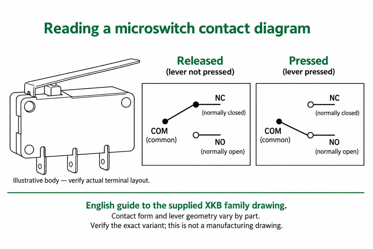
The manufacturer drawing covers a family of lever and contact variants, so on its own it cannot establish the mounting or travel clearance of your complete module.
Check the electrical interface, then keep the test simple
We used the DIO0 connector with GPIO6 as the signal; the other GPIO at that connector was unused. Released reads HIGH and actuated reads LOW. Before reproducing that connection, check the output voltage. A module that pulls OUT up to a 5 V supply should not drive a 3.3 V controller input directly without suitable interfacing. Measure OUT with the supply you will actually use, and verify the module revision and interface before powering a new arrangement.
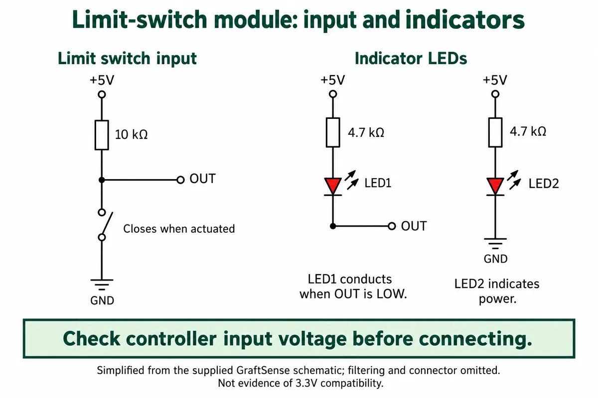
The circuit has a power indicator and a state indicator. As drawn, LED1 has a current path from +5 V through its resistor to OUT when OUT is LOW. Use the measured signal and the checked circuit to interpret the state, rather than assuming "light on" always means "released."
The test program used a small limit-switch class from our team's driver library. It reports switch changes through a callback and prints the current input once per second. The terminal recorded both the periodic state reports and the press and release notifications while we operated the lever by hand. That is a physical input demonstration, not a moving carriage stopping at a known distance.
Understand what the driver actually filters
Check what a driver's "debounce" setting actually does. In the driver we used, the 50 ms setting is a sampling interval: it samples the pin every 50 ms and reports a change from the previous sample. It does not require the input to stay unchanged for 50 ms before accepting it. Its read method returns the live pin level, not the last reported state.
That matters when you build on it. A short event can fall between samples, and a noisy transition spanning samples can produce several notifications. The callback is deferred through MicroPython's micropython.schedule, and the one-second terminal print is a separate activity. None of these intervals is a measured stopping time for a mechanism.
For the next test, log the signal while operating the actual mechanism slowly and confirm that one physical actuation produces one expected transition. Choose filtering and sampling around the real motion and required response; do not inherit 50 ms as a universal value.
A home reference needs a sequence
Recognizing the switch gives the controller a physical observation. Homing adds the behavior around it: where to move, what to do if the switch is already active, how to leave it and how to establish a repeatable reference.
The Grbl homing documentation illustrates this with an approach, a switch trigger, a back-off and a slower second approach. It also bounds the search travel. That comes from a different motion-control system, but the sequence carries over.
For a small moving display, a useful next prototype would test more than a normal startup. It would also start with the switch already pressed, and it would stop the search on a missing or unexpected signal instead of continuing indefinitely. Speed, travel limits and stopping behavior need to be designed for that mechanism. A bench module like this is not a substitute for a safety-rated motion system.
Mount it where the mechanism can operate it consistently
Leave room for the lever to move and return. Check where the mechanism first actuates it, how much further the mechanism travels before stopping and whether the mounting can shift after repeated operation. A supplier drawing or the click of a switch does not establish the assembled mechanism's repeatability.
The useful handoff to engineering is a short record: the actual input levels, the chosen mounting position, the controller behavior at startup and repeated observations of the resulting home position.