
For a small controller or an interactive exhibit, a row of lights can be easier to notice than a number on a screen. The difficult part is deciding what those lights mean. Six lit segments could mean a setting of six, six completed steps, or an estimated level. Those are different promises to the person using the device.
A useful example appears in an October 2022 Arduino discussion. The builder wanted an oil-tank simulator whose bar rose or fell when switches were operated. It was a teaching display driven by a stored value, not a tank sensor. That distinction helps frame the first prototype: prove the display behavior, then connect it to the information it is meant to represent.
On our bench we ran that first display experiment with a GraftSense eight-segment LED-bar module, built around a PCF8574 I/O expander, connected to a GraftPort-RP2040 controller board running MicroPython. We found its I2C address and played a short pattern sequence. Here is what that sequence can and cannot help you decide.
Start with a display you can control
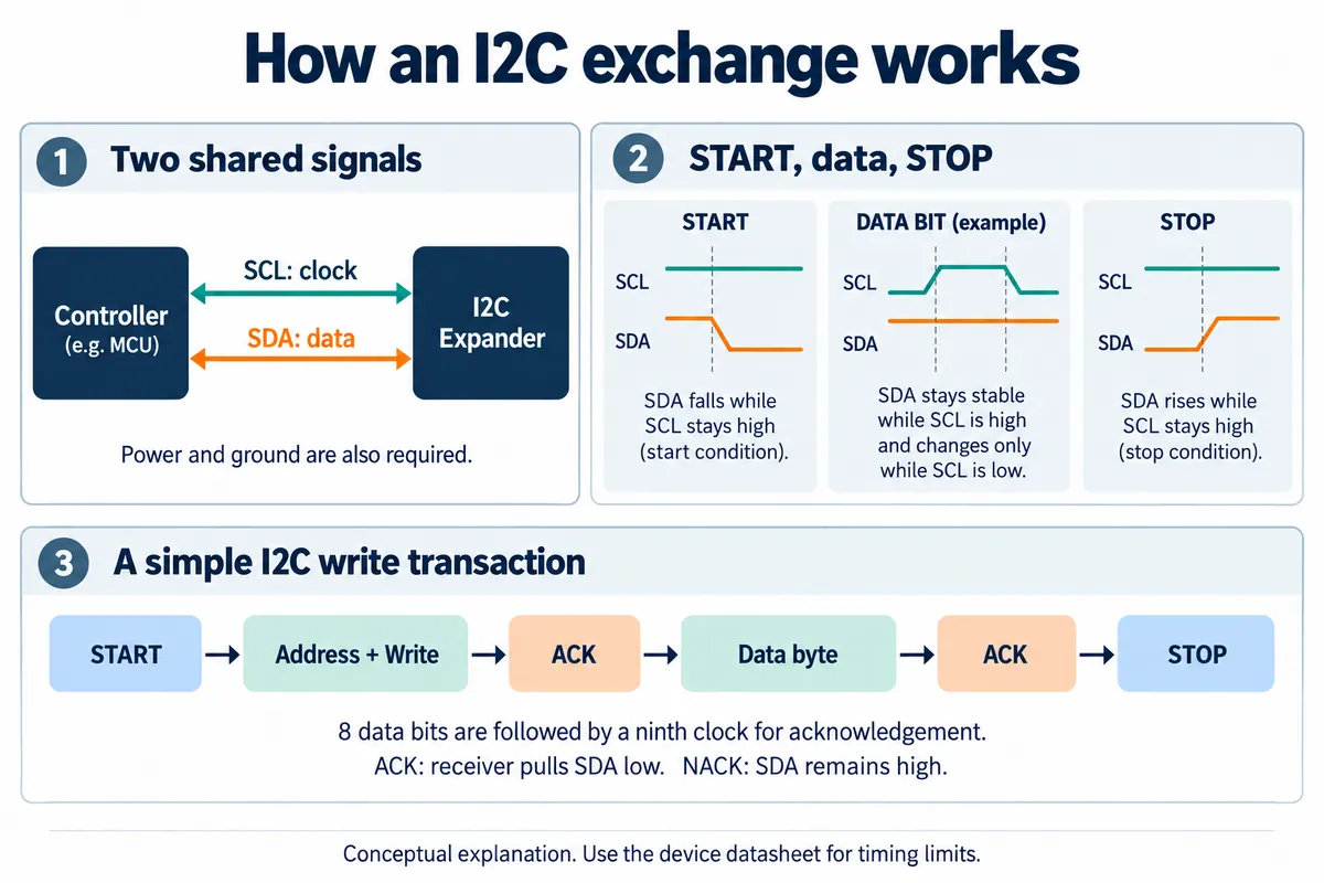
The module puts eight LED segments behind an I2C interface, so the controller sends commands over a shared data line and clock line. Our test code used I2C0 with GP4 for SDA, GP5 for SCL and a 100 kHz clock. Power and ground are also required; a signal-pin table alone is not a complete wiring specification.
The board has address-selection pads as well as the four-pin connector, so the program can address this module without confusing it with another device on the bus. Check the particular board revision and supply arrangement before reproducing the wiring: a broad "3.3 V/5 V compatible" label is not enough to establish every controller combination.
In our run, the scan found one device at 0x20. That is the seven-bit address used in the MicroPython call. Some reference tables instead show 0x40 and 0x41: those are address bytes with the write or read bit included. Passing an address byte where the API expects a seven-bit address creates a different request. The NXP PCF8574 datasheet documents this distinction.
Our first test program passed the loop variable from its scan straight into the driver constructor. If another device is last in the list, that selects the wrong address; if the scan is empty, the variable is never set. For a board known to use 0x20, a clearer setup looks like this (we have not rerun this exact version on hardware):
from machine import I2C, Pin

i2c = I2C(0, sda=Pin(4), scl=Pin(5), freq=100000)
address = 0x20  # Match the address selection on this board.
if address not in i2c.scan():
    raise RuntimeError("LED bar did not respond at its expected address")
An address response tells you that something answered there. Use the module's known configuration and a simple visible pattern to finish identifying it.
Keep the driver and the demonstration together
The LED-bar driver package we installed needs attention before reuse. Its lower-level pcf8574.py file contained a path to another driver rather than the Python implementation itself. The higher-level LED-bar class was present, but the package alone was not a working installation. Obtain the matching dependency and check the installed files on the board before expecting a demonstration to run.
With the dependency in place, the program builds a PCF8574 object on the I2C bus and passes it to the LED-bar class. Our demonstration then requested these operations:
| Operation | What it is meant to show |
|---|---|
set_led(2, True), then False |
Switch the third indexed segment on, then off |
set_all(0b00001111) |
Apply a four-bit pattern |
display_level(6) |
Request a level of six segments |
set_all(1 << i) for eight positions |
Move one selected bit along the bar |
clear() |
End the demonstration |
The script pauses for one second between the first operations and 0.2 seconds between moving-light steps. On the bench the physical bar changed its pattern through the sequence. The run did not include a sensor input or a battery measurement.
One more detail needs checking on the actual assembly. The driver class writes the requested bits directly, and its clear() method writes zero. Whether that makes a particular LED light or go dark depends on the carrier wiring and the lower-level driver. Check a single segment before treating the method names as proof of electrical polarity.
Give the pattern a meaning before adding more features
For an adjustable setting, a filled bar can show the selected level. For a process with eight defined steps, it can show completed steps. A moving point can suggest activity, but only if the underlying task is still running. These are possible uses of the patterns we ran, not functions we have implemented.
Try the bar behind the intended front panel and view it from the distance your user will stand. Decide which end means "low," add a label where needed, and check whether adjacent segments remain distinguishable through the cover. Board artwork can help you locate the segments, but it cannot answer those viewing questions.
Also decide how to distinguish zero from "no valid reading." If both leave every segment dark, the user cannot tell an empty measurement from a disconnected input. A separate status indication or a deliberately different pattern may help; choose it as part of the interaction and test whether people understand it.
The next useful milestone is one complete interaction: change a setting or provide a known input, observe the correct pattern, then remove that input and observe the defined fallback.