
Your prototype now reads two analog sensors instead of one. Both numbers change, the graph looks plausible, and the file fills with data. Before using that record to compare the sensors, check a less obvious question: does every value still belong to the input named beside it?
This matters when a program collects alternating inputs into one stream and separates them afterwards. On the RP2040 that is what round-robin sampling into the ADC result FIFO does. This note works from the RP2040 hardware reference rather than a recorded two-sensor experiment, and it sets out how to reason about the data before trusting the labels.
For a small team building a two-input instrument, the useful next step is a channel-identification test. It should cover the first capture, another capture after stopping, and any interruption that loses samples. A convincing graph cannot answer those questions.
Establish which input comes first
The RP2040 has one ADC converter with selectable inputs. In round-robin mode it visits the enabled inputs in turn; it does not measure them all at the same instant. The official ADC API reference distinguishes the selected input from the round-robin input mask.
With an initial selection of AINSEL = 0 and a mask of RROBIN = 0x06, the first conversion is channel 0, followed by channels 1 and 2 alternating. The first selection need not belong to the repeating set. A program that assumes the buffer starts with channel 1 labels the very first result incorrectly.
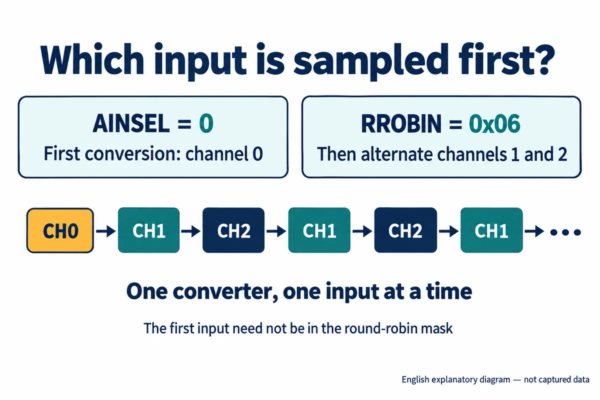
These channel numbers are hardware inputs, not connector numbers or sensor identities. Record the connection from each sensor to the board input before calling one of them "left sensor."
If the repeating sequence is A, B, A, B, software can split alternating entries into two arrays, but only after establishing that the first entry is A and that no entries were lost. Treat those conditions as part of the data format, not an assumption buried in the plotting code.
The storage question shows up in an April 2023 MicroPython discussion. The author wanted two input streams for a software-defined radio and asked how to place the interleaved samples in separate arrays. Replies explored DMA arrangements; the thread did not report a completed hardware test. The relevant point is that the array layout has to be defined before it is interpreted.
The FIFO value does not carry a sensor name
The FIFO is a short queue of conversion results. DMA can move them into memory without the processor copying each one. Moving them efficiently adds no information about which sensor produced them.
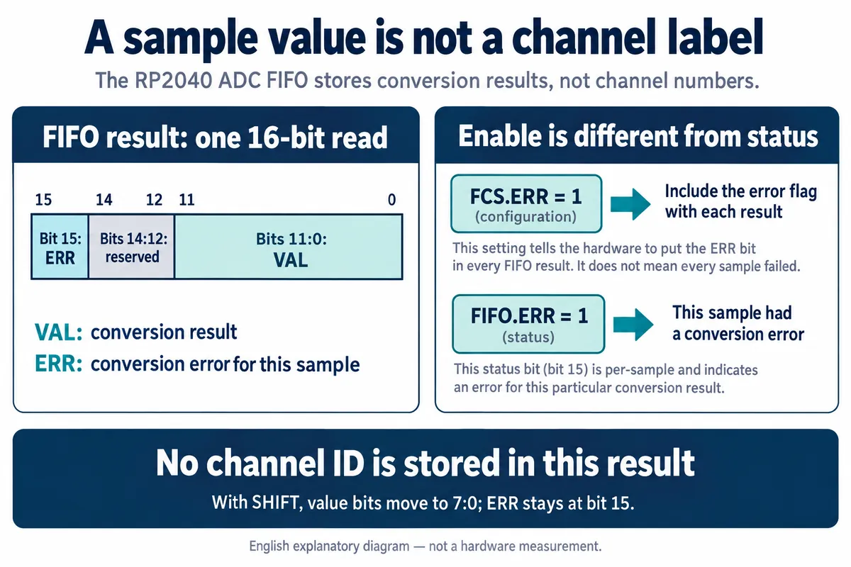
Each result contains a conversion value and an optional error flag, with reserved bits between them. There is no channel-ID field. An application that relies on alternating positions has to preserve the link between the conversion sequence and the stored sequence.
Two similarly named fields do different jobs. FCS.ERR enables inclusion of the error information; FIFO.ERR reports a conversion error for a particular result. Enabling the feature does not mean every sample failed.
If an invalid conversion appears, keep its place in the channel sequence and mark its value unusable. Deleting it from the combined stream before separating channels would shift every later value into the wrong position. That is a consequence of positional labeling, not an ADC feature.
Also agree on the stored width. An optional shift reduces results to eight value bits, saving space at the cost of the lower bits, while the error flag stays at bit 15. An eight-bit memory transfer does not carry that flag along with the value, so the capture format needs an explicit error-handling plan.
A lost sample can become a wrong label
The RP2040 datasheet's sample-FIFO section explains that a conversion arriving at a full FIFO is lost and sets the overflow flag. Existing entries are not overwritten. The flag says a loss occurred; it does not reconstruct the missing values.
Take a hypothetical alternating stream. If A1 is lost, the stored values run A0, B0, B1, A2, B2. A decoder that keeps taking every other entry as A will call B1 an A reading. Losing two entries may leave the alternation aligned while still leaving a gap in time. Both cases need handling.
The FIFO control and status register separates overflow, underflow, current level and configuration. Clearing an overflow flag acknowledges a condition; it does not prove the next buffered entry belongs to the channel your display expects.
For an early prototype, a defensible policy is to mark the affected capture invalid, stop acquisition cleanly and start again from a known channel boundary, with the engineer defining how that boundary is set. If uninterrupted measurement is essential, that requirement should drive the acquisition design and its tests rather than being hidden by a continuously moving plot.
Give each capture a deliberate beginning and end
A sound DMA setup chooses the first input, sets the repeating inputs and configures the rate before starting conversion, and starts DMA first so a receiver is ready for the results. At the other end, stopping repeated conversion is followed by waiting for the current conversion to finish and draining what remains in the FIFO.
That gives "capture again" a clear meaning: a fresh, identified sequence, not whatever was left in a queue. The SDK documentation for draining the ADC FIFO describes waiting for an in-progress conversion and discarding remaining results. These are C SDK operations; use the equivalent for your actual firmware, as they are not automatically MicroPython methods.
An interrupt at a configured queue level tells you data is waiting. It does not name the first channel or prove there were no earlier losses. Keep acquisition status with the record the application will display or export.
A capture record could include the channel order, first-channel identity, number of retained results, configured rate and any acquisition errors. For two equally alternating channels, the total conversion rate is shared between them. Adjacent A and B values were also taken at different instants. If the measurement needs simultaneous values, establish the acceptable time offset before committing to this approach.
Test the labels before testing a complicated signal
Start with two distinct, stable, known-safe input levels chosen for the actual board. Hold one steady and change only the other. Check the raw capture as well as the displayed traces: only the intended channel should respond. Repeat after stopping and restarting the capture and after resetting the device.
Then run the other tasks the finished demonstration needs, such as screen updates and file output, and test the chosen overflow policy under controlled conditions. The expected result when continuity is lost is a clearly invalid or interrupted record, not a plausible trace silently assigned to the other sensor. These are proposed acceptance tests; we have not run them yet.
Touching a floating ADC pin and watching the number change is a fine way to learn the API. It does not provide known input values or validate a multi-channel data format. Move to controlled inputs once the question is whether the labels and measurements can be trusted.