
You are building a handheld controller, a small instrument or an interactive exhibit. It needs a way to move through choices, and a thumb joystick looks like a convenient answer. But should a slight movement move one menu item, keep scrolling, or change something continuously? That decision matters more than the shape of the control.
On our bench we tried three GraftSense input modules on a GraftPort-Pico controller: a PS2-style joystick that reports two changing voltages, a five-way switch module that reports named button states, and a wheel switch for simple up and down actions. The tests demonstrate the inputs. They do not yet demonstrate a finished menu or a tested handheld product.
Start with what the user should be able to do
A joystick makes sense when the amount of movement matters: moving a cursor, exploring a scene, or adjusting two parameters together. A directional switch is a more direct starting point for stepping through a short list and pressing to confirm. Either can work for navigation, but neither decides how a held direction should behave.
In an April 2023 Babylon.js discussion, a developer had already added a joystick dead zone, yet menu selection still jumped between choices because the input advanced the menu on every qualifying frame. Waiting for a return to neutral before accepting another move solved it. The lesson for a hardware prototype: test the intended action, not just whether numbers change.
Keep the first task small: let someone select one item, return to the previous item and confirm. Watch whether they overshoot, confirm by accident while moving, or need to look down at the control. These are the usability checks to run next; our bench tests did not include them.
Joystick: two axes, and no tested press
The joystick contains two variable resistors, one per axis. We read VRX on GPIO28 and VRY on GPIO27; the four-wire connector also carries power and ground. Check the actual connector order rather than copying wire colors from a photo.
Our test program, built on our team's joystick driver, sampled at 10 updates per second and printed the latest values every 0.2 seconds. The terminal showed changing X and Y values, including readings around 2.70 and 1.49. These are filtered voltage estimates, not angles. The driver multiplies the ADC reading by 3.3 / 65535, then combines 20% of the new reading with 80% of the previous filtered value. That smooths changes but also delays the response. Its starting value of 1.55 is a software initial value, not a measured center.
Another detail is easy to miss: the program supplied no switch pin, so its printed Switch = 1 is the driver's default, not proof that pressing the stick was detected. The four-wire connection carries only the two axes, power and ground. Do not design press-to-confirm on the assumption that this test covered it.
To turn readings into menu movement, record where the stick actually rests, define a small neutral region around it, then decide whether a deliberate push causes one step or starts a timed repeat. Smoothing and a neutral region solve different problems: smoothing reduces jitter between readings; the neutral region decides when to do nothing. We have not built a calibrated menu control on top of this yet.
The module schematic labels the axis supply 3.3 V but names a regulator whose part number needs reconciling with that label. Confirm the fitted regulator and actual voltage before treating the printed values as calibrated. The test shows changing input, not absolute voltage accuracy.
Five-way switch: directions and confirmation on I2C
The five-way module combines up, down, left, right and a center press, plus two separate buttons. A PCF8574 expander puts these states on an I2C bus, so the host does not need a GPIO for every button. The key map places UP on P0, LEFT on P1, RIGHT on P2, DOWN on P3, CENTER on P4, SW1 on P5 and SW2 on P7, with P6 driving an indicator. Confirm orientation with the board in its intended mounting position before assigning screen actions.
We used I2C0 with SDA on GPIO4 and SCL on GPIO5. The program scanned the bus, printed button states every 100 ms and used SW1 and SW2 to turn the indicator on and off. The recorded terminal printed press and release labels.
Our records for this module need cleaning up before anyone replays the test. The driver package we have returns Boolean values rather than those labels, so it is not proven to be the version that produced the capture, and one of its dependency files contained only a path instead of the implementation. More importantly, the key driver writes whole-port values that drive the key bits low. With normal PCF8574 behavior, input bits must be released high to be read, as the micropython-pcf8574 driver by mcauser documents. Get the matching schematic and driver before treating the package as ready to run.
Share the bus without guessing the address
The address straps matter when this board shares I2C with a display or another module. For the PCF8574, three address bits select 0x20 through 0x27.
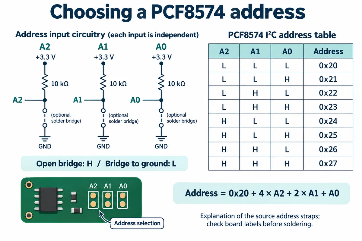
Our scanner also accepted 0x28 and kept the last matching address, which is not a reliable way to find this board on a bus with several devices. Select and check the intended address explicitly, and decide what the program does if nothing responds. We ran the bus at 400 kHz, but the specification sheets we had mix vendor variants; verify the fitted part's bus limit before reusing that setting.
Wheel switch: when up and down are enough
If someone only needs to move to the next item or nudge one setting, a small rocking wheel may be enough. It offers a different thumb motion from separate buttons without asking software to interpret a joystick voltage. It is a switch with limited travel, not a continuously rotating encoder.
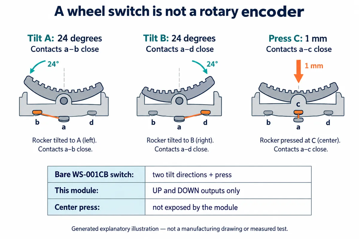
The bare WS-001CB part supports two tilt directions and a press, but the module uses only the two directions: pressing the middle produces no output. If the task needs confirmation, add another control or choose a module that exposes that contact.
We wired UP to GPIO14 and DOWN to GPIO15. Both idle high and go low when operated. The board's connector labels conflict in places, so follow the actual pin mapping and the program's GPIO numbers. The schematic pulls each signal to VCC through 10 kOhm with 100 nF to ground; check VCC against the host's input limits first.
The terminal recorded both directions being detected. In our driver, a change restarts a 20 ms one-shot timer for that channel, and after the delay the driver checks the state and calls the direction callback on an accepted transition. That separates contact chatter from a deliberate action. It does not implement scrolling speed or repeat-while-held; those belong to your interface design. Use the callbacks to record an event for the main application to handle.
Try the control in the shape of the product
A successful bench read tells you an input path exists. It does not tell you whether a thumb can reach the control through a panel, whether the cap strikes the opening, or whether a center press causes an unintended direction. A simple enclosure mock-up can answer those questions before the PCB and mechanical layout are fixed.
For a short menu, start by testing one step per deliberate direction press, a visible selected item and a distinct confirmation action. For longer lists, try a delayed repeat while held. For continuous control, measure center and endpoints, choose a neutral region, and test the trade-off between smoothing and response. Our recordings do not pick a universal winner; they tell you which experiment to run next.