
You move a hand away from a sensor and the distance on screen stops at 80 cm. Has the hand stopped moving? Has the sensor lost it? Or has the software decided never to display a larger number? If you are building a touchless control or a simple measuring fixture, those possibilities lead to very different behavior.
The difficulty is not unusual. In an Arduino discussion from August 2023, a builder reported a distance returning to an unexpected value as the target moved away. The thread did not establish a cause. It shows why a plausible number needs to be traced back through the sensor and software before it becomes a product decision.
We ran two bench experiments with GraftSense infrared distance modules on a GraftPort-RP2040 controller board under MicroPython. One reads an analog Sharp GP2Y0A21YK-family module through the ADC; the other reads a GP2Y0E03 module over I2C. Both produced changing readings as a hand moved. They were separate demonstrations, not a controlled accuracy comparison.
Start with what the analog module actually sends
The analog sensor sends a voltage, not a number of centimeters. The controller's analog-to-digital converter (ADC) turns that voltage into a number, and a driver then estimates distance from it. Each stage contributes something to the final display.
In our setup the module connected to the board's AIN0 connector and the program read GP26. When using a different carrier, verify power, ground and signal pin order against that revision; a cable that fits does not establish electrical compatibility.
Power deserves a separate check. The Sharp GP2Y0A21YK0F datasheet specifies a recommended 4.5–5.5 V sensor supply. That is different from the 3.3 V our software used as its assumed ADC reference. Setting that variable does not power the sensor or change the controller's allowed input voltage.
This distinction solved a real user's problem: in a May 2020 Arduino thread, the author measured only 4.29 V at the sensor supply and reported normal behavior after correcting it. Their board and supply were different, so the lesson is to measure the actual rail, not to copy their wiring.
Follow the conversion into centimeters
Our analog test used version 1.0.0 of our GP2Y0A21YK driver with five-sample averaging, a 3.3 V reference setting and a nominal 500 ms print interval. It printed raw ADC data, millivolts and estimated centimeters, and labeled readings "close" below 20 cm and "far" above 40 cm. Those thresholds are examples, not tested requirements for a finished interface.
The driver estimates distance as 29.988 × (voltage in volts)^-1.173, rounds to whole centimeters, and limits a positive result to 10–80 cm. That is a nonlinear conversion: halving the voltage does not simply double the distance. Sharp's response curve also bends, and reverses direction at the very close end, outside the specified working range.
In our terminal log, the last three readings had different voltages but all showed 80 cm. The driver's upper limit explains why the display can stay at 80 even while its input changes. The log does not establish that the target was physically 80 cm away.
The lower limit needs the same care. Clamping a calculated value to 10 cm cannot reliably recognize everything closer than 10 cm, because the optical response outside the working range is not a unique distance-to-voltage relationship. A tidy endpoint on screen is not a substitute for an explicit "reading unavailable" condition.
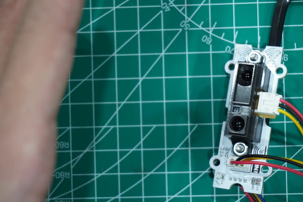
There was no ruler comparison or error table in this test. Treat the changing values as a bring-up result: the assembly produces readings that respond to the target. To make a dimensional claim, add a known distance and record the difference.
The digital module removes one conversion, not every uncertainty
The second experiment used the GP2Y0E03 over I2C. The sensor returns encoded distance data, so the controller does not measure an analog output. We connected it to I2C0 with GP4 for SDA and GP5 for SCL, ran the bus at 100 kHz, and found the module at address 0x40, using version 1.0.0 of our GP2Y0E03 driver. An address response is a useful first check that the interface is reachable. It does not establish that the target is in range or that its distance is accurate.
The driver combines two distance-register bytes into a 12-bit raw value and scales it using the sensor's shift setting. With the shift value of 2 we read back, the conversion is raw / 64 centimeters. Unlike the analog driver, this distance method does not clamp its result to the manufacturer's stated 4–50 cm measuring range.
That explains the conspicuous 4095 and 63.98 cm entries in our log. The arithmetic can produce 63.98, but the number is beyond the specified range. It is not a measurement of a target at that distance, and our record does not show what physical condition produced those entries.
Likewise, two decimal places do not demonstrate hundredth-of-a-centimeter accuracy. Under the Sharp datasheet's specified test conditions, the table gives a 45–55 cm output interval for a target at 50 cm. Those conditions include a particular reflective target and lighting; the much finer display increments describe numerical representation, not the error of this assembly.
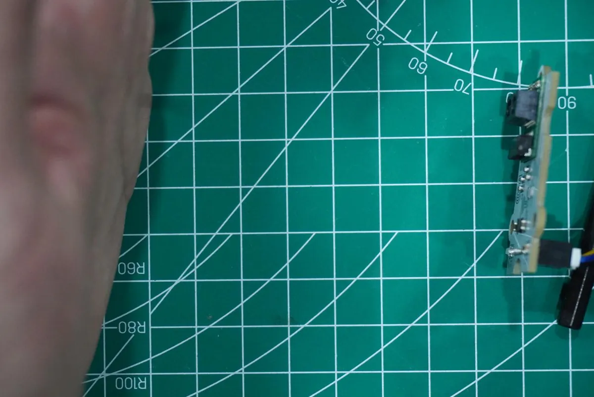
These two runs help compare the integration steps: ADC reference and voltage conversion versus bus setup and register scaling. They do not establish which module is more accurate in your product.
Keep one observation together
There is a small software detail that matters when the target moves. In both programs, separate method calls acquire fresh data. The digital test read once for the raw value and again for the distance. The analog test read raw data, took an averaged voltage, read again for distance, and read again inside each threshold check.
So the fields on one printed line are not guaranteed to describe the same instant. That need not block a first demonstration, but it can confuse calibration: you might compare one voltage with a distance calculated from another set of samples. Capture a sample once and derive the displayed value and threshold decision from that observation.
| Keep in a trial record | Why it helps |
|---|---|
| Raw reading and conversion settings | Shows how the displayed number was obtained |
| Estimated distance and range status | Separates a usable estimate from an endpoint or out-of-range value |
| Known target position and material | Makes error and repeatability comparisons possible |
| Timestamp and application decision | Shows which observation triggered the response |
Also check disabled and missing-signal behavior: the analog driver can return zero for a nonpositive voltage, and a plain "less than 20" comparison would then classify it as close.
Decide what your prototype needs to know
If your object only needs to react when a hand enters a zone, first test whether that zone behaves consistently across the expected approach positions. You may not need to show centimeters at all. If the prototype must measure a part or position a mechanism, specify the allowable error and add reference measurements before choosing a module on the strength of its display resolution.
For either use, start with a fixed target at several known positions inside the sensor's specified range. Log repeated readings without moving it, then change the distance. Separately record what happens with no target and with a target closer than the working range. Do not fold those conditions into the nearest valid endpoint and call them measurements. These are the next tests to run; our two hand-target experiments do not answer them.